CR60-L500 - Installation
Installation at a minimal distance from another damper or from an adjacent supporting construction
Principle
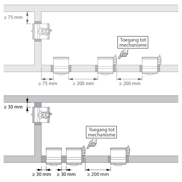
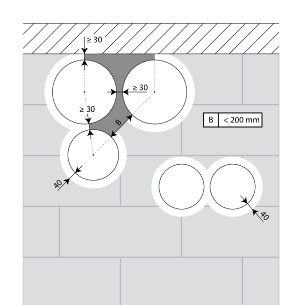
According to the European test standard, a fire damper must be installed at a minimum distance of 75 mm from an adjacent wall and 200 mm from another damper, unless the solution was tested at a shorter distance. This range of Rf-t fire dampers has been successfully tested and can be installed in a vertical or horizontal supporting construction, at a distance below the minimum set by the standard.
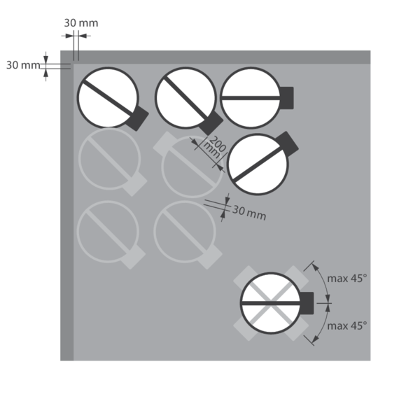
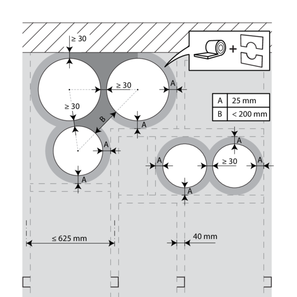
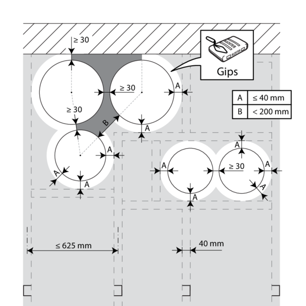
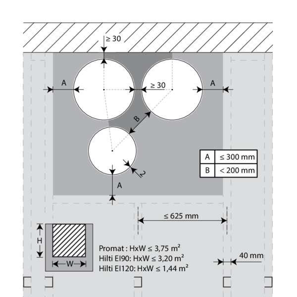
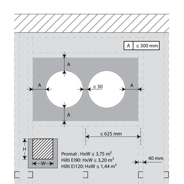
For circular dampers, the minimal distance is set to 30 mm.
According to the European test standard, a fire damper must be installed at a minimum distance of 75 mm from an adjacent wall and 200 mm from another damper, unless the solution was tested at a shorter distance. This range of Rf-t fire dampers has been successfully tested and can be installed in a vertical or horizontal supporting construction, at a distance below the minimum set by the standard.
For circular dampers, the minimal distance is set to 30 mm.
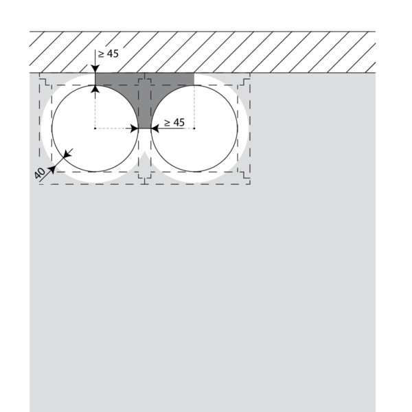
Certified solution
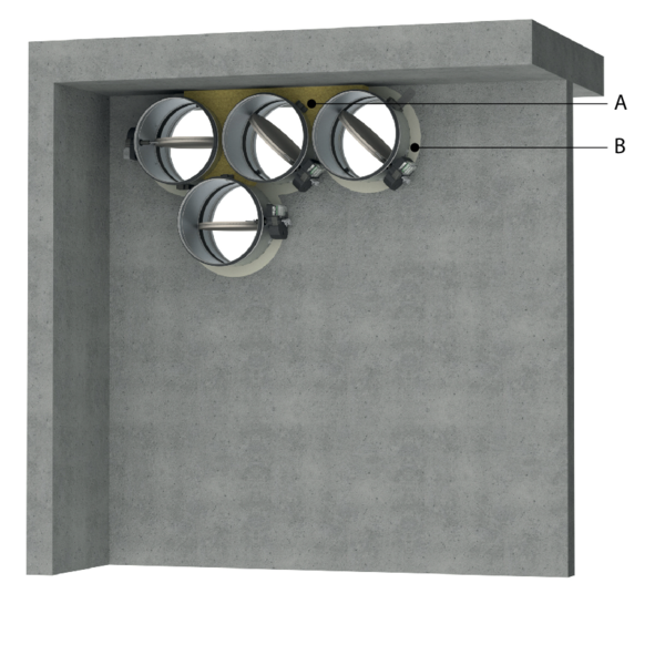
For the Rf-t fire dampers, the solution consists of the following elements: A: Universal sealing for minimal distance; B: Sealing compliant with existing classifications (Declaration of Performance).
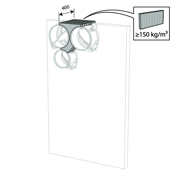
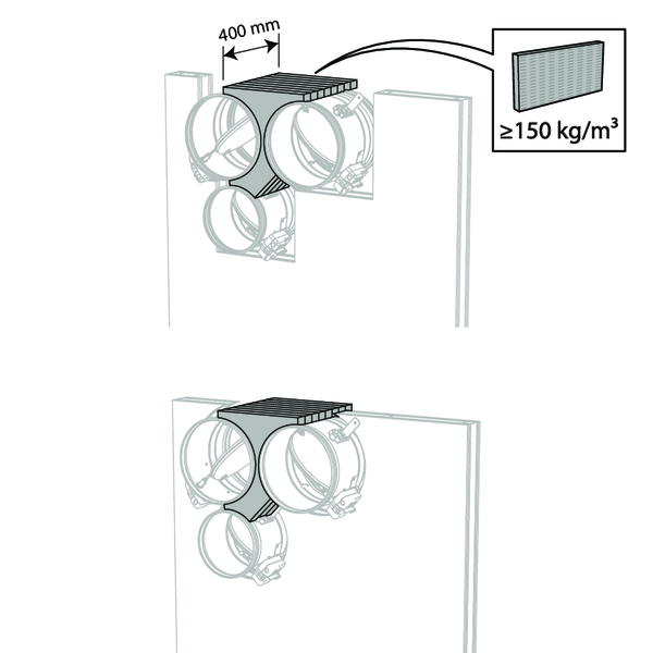
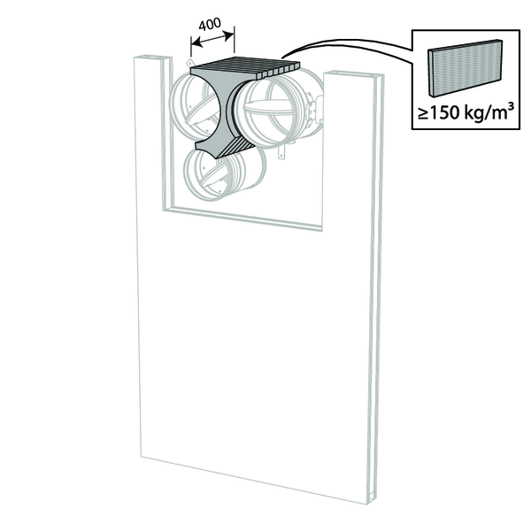
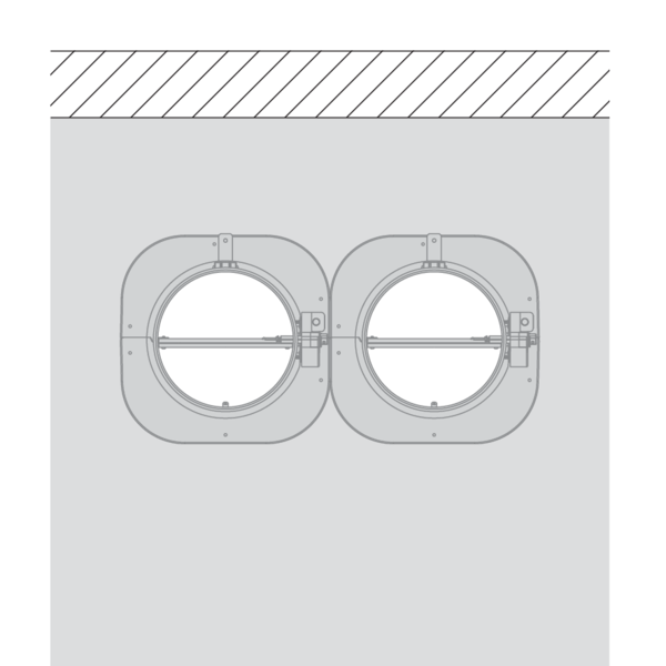
A. Sealing of the opening at the side with minimal distances between damper and wall/ceiling or another fire damper: rigid stone wool panels (150 kg/m³) are applied to a depth of min. 400 mm, of which 150 mm on the mechanism side of the wall. On the non-mechanism side of the wall, the stone wool panels must be at least flush with the wall.
The surface of this sealing is set between the axes (centres) of the dampers.
B. Sealing of the rest of the opening according to the existing classifications for the fire damper (Declaration of Performance).
This also applies to circular dampers that are mounted at a minimum distance from one another (30 to 200 mm) but at a distance greater than 75 mm from a wall/ceiling.
Detailed information for each wall/sealing combination can be found in the respective installation methods.
For the Rf-t fire dampers, the solution consists of the following elements: A: Universal sealing for minimal distance; B: Sealing compliant with existing classifications (Declaration of Performance).
A. Sealing of the opening at the side with minimal distances between damper and wall/ceiling or another fire damper: rigid stone wool panels (150 kg/m³) are applied to a depth of min. 400 mm, of which 150 mm on the mechanism side of the wall. On the non-mechanism side of the wall, the stone wool panels must be at least flush with the wall.
The surface of this sealing is set between the axes (centres) of the dampers.
B. Sealing of the rest of the opening according to the existing classifications for the fire damper (Declaration of Performance).
This also applies to circular dampers that are mounted at a minimum distance from one another (30 to 200 mm) but at a distance greater than 75 mm from a wall/ceiling.
Detailed information for each wall/sealing combination can be found in the respective installation methods.
Restrictions
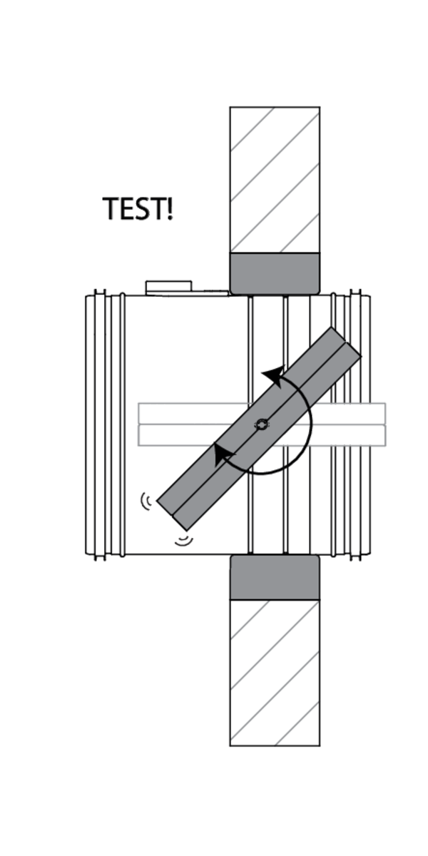
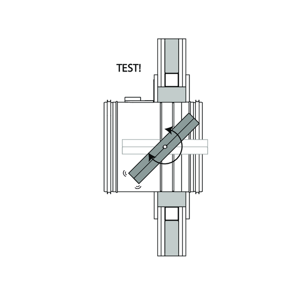
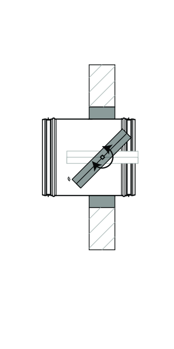
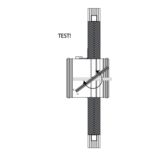
The orientation of the blade axis should be horizontal or oriented at a maximum of 45°.
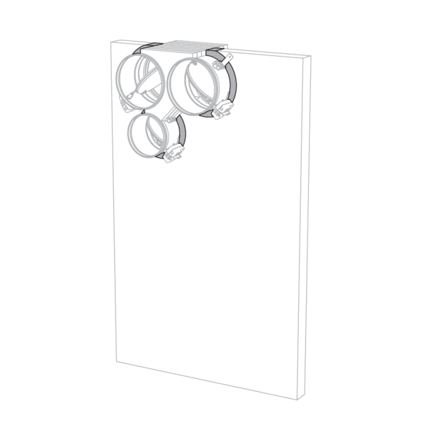
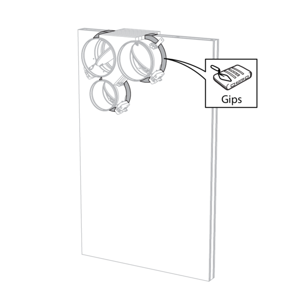
A maximum of 3 circular dampers can be installed at a minimum distance from one another, both vertically and horizontally (with a maximum cluster of 4 dampers).
Note: when sealing the opening with panels of fire resistant stone wool, the maximum number of dampers also depends on the maximum “blank seal” allowed for the selected sealing material. Please refer to the manufacturer's instructions for this information.
Note: Separate conditions apply for installation in flexible shaft wall. Detailed information can be found in the relevant installation methods.
The orientation of the blade axis should be horizontal or oriented at a maximum of 45°.
A maximum of 3 circular dampers can be installed at a minimum distance from one another, both vertically and horizontally (with a maximum cluster of 4 dampers).
Note: when sealing the opening with panels of fire resistant stone wool, the maximum number of dampers also depends on the maximum “blank seal” allowed for the selected sealing material. Please refer to the manufacturer's instructions for this information.
Note: Separate conditions apply for installation in flexible shaft wall. Detailed information can be found in the relevant installation methods.
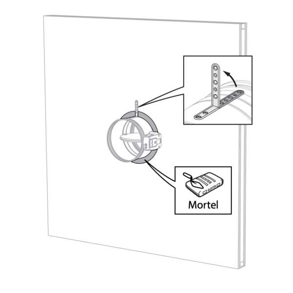
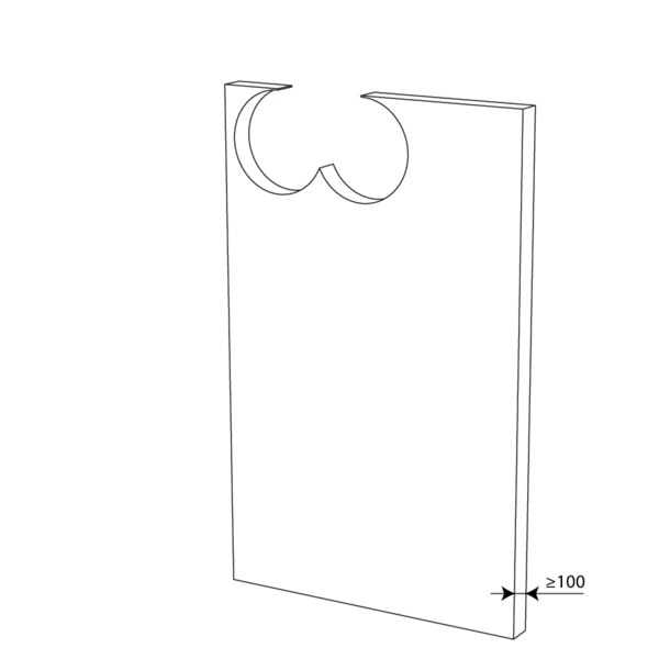
Installation in rigid wall and floor
The product was tested and approved in:
- Aerated concrete ≥ 100 mm | EI 90 (ve i o) S - (500 Pa) | Mortar / Gypsum | Type of installation: built-in, 0-360°. Minimal distances authorised with axis till 45°. | Ø 100-315 mm
- Aerated concrete ≥ 100 mm | EI 90 (ho i o) S - (500 Pa) | Mortar | Type of installation: built-in, 0-360°. Minimal distances authorised. | Ø 100-315 mm
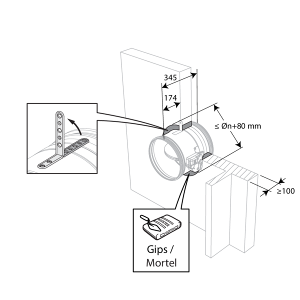
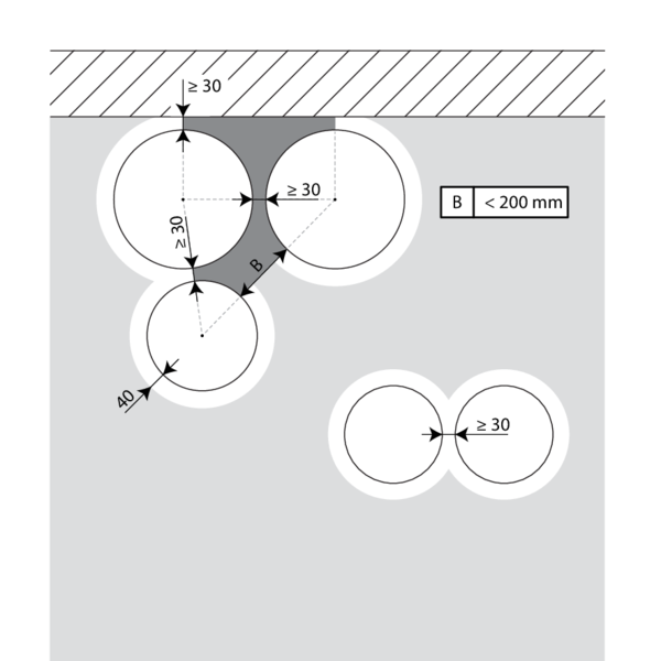
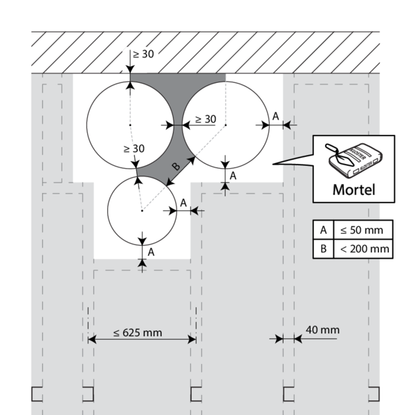
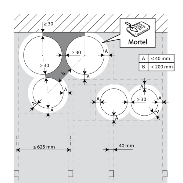
The dampers can be installed at a minimum distance (≥ 30 mm) from an adjacent wall or from another damper.
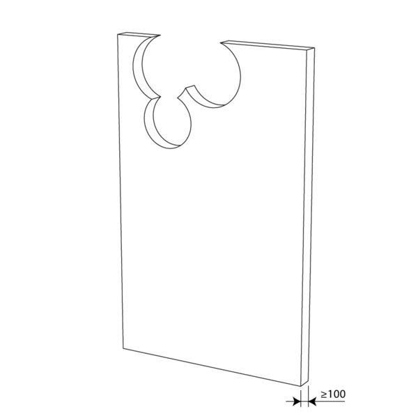
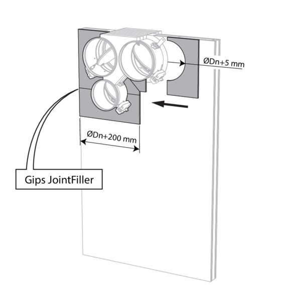
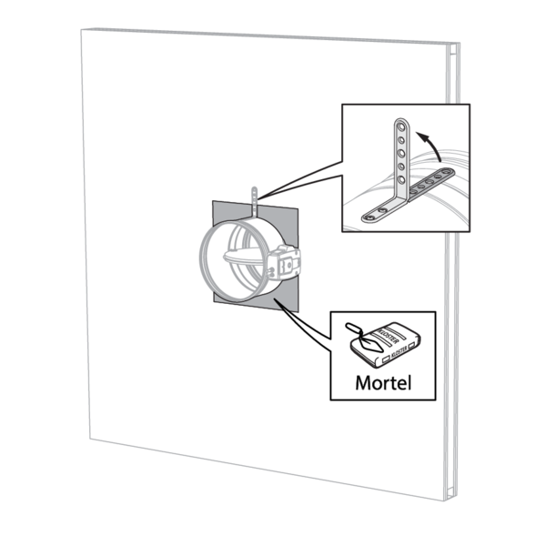
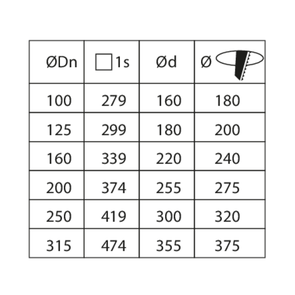
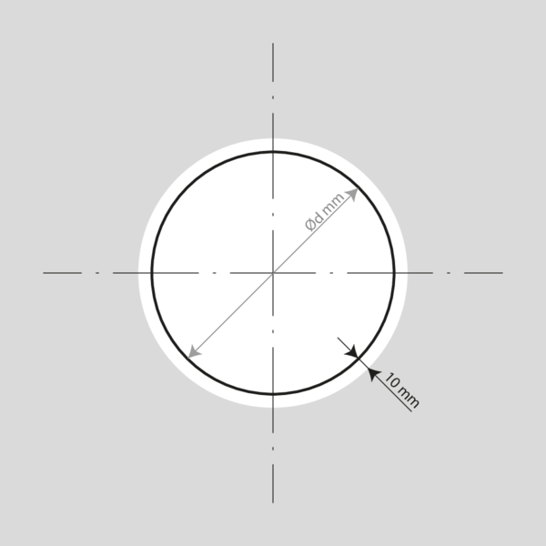
Make the necessary openings (≤ Dn + 80 mm) in the wall.
Mount the dampers in the opening.
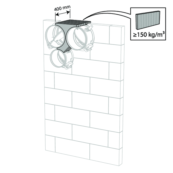
Apply rigid stone wool panels (≥ 150 kg/m³) to a depth of 400 mm (150 mm on the mechanism side of the wall) to seal the opening at the side with minimal distances.
The surface of this sealing is set between the axes (centres) of the dampers.
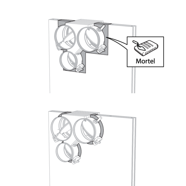
Caution: the opening is sealed according to the existing classification (see next point) when: - 2 fire dampers are installed at a minimum distance from one another but at a normal distance (≥ 75 mm) from the wall or floor/ceiling. - One single (no cluster) fire damper is located at a minimum distance (≤ 75 mm) from a wall or floor/ceiling.
Apply rigid stone wool panels (≥ 150 kg/m³) to a depth of 400 mm (150 mm on the mechanism side of the wall) to seal the opening at the side with minimal distances.
The surface of this sealing is set between the axes (centres) of the dampers.
Caution: the opening is sealed according to the existing classification (see next point) when: - 2 fire dampers are installed at a minimum distance from one another but at a normal distance (≥ 75 mm) from the wall or floor/ceiling. - One single (no cluster) fire damper is located at a minimum distance (≤ 75 mm) from a wall or floor/ceiling.
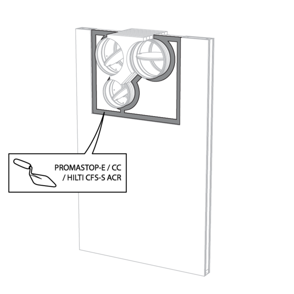
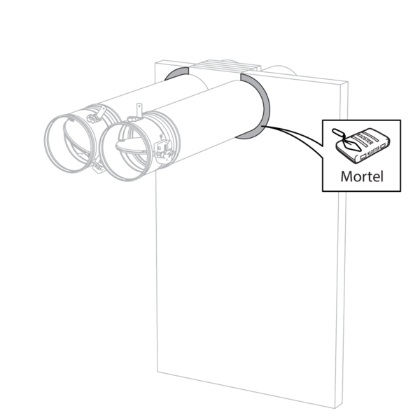
Seal the rest of the opening with standard mortar or gypsum (only for vertical walls).
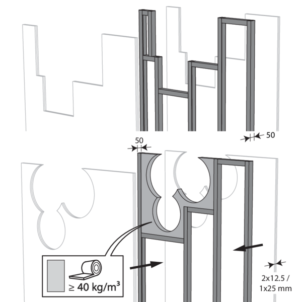
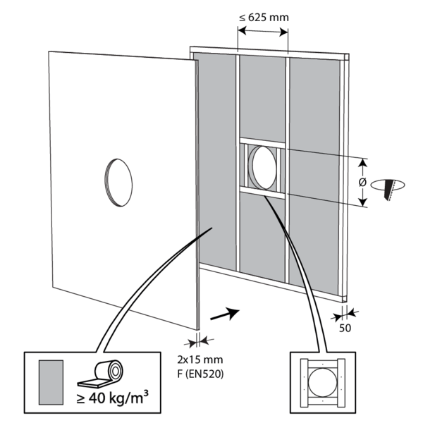
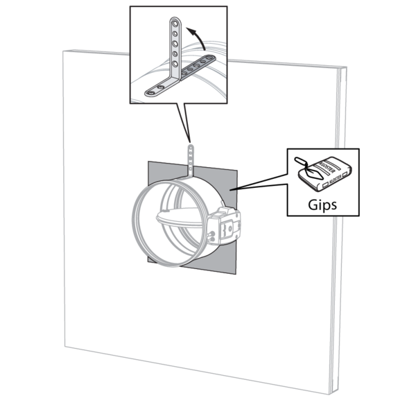
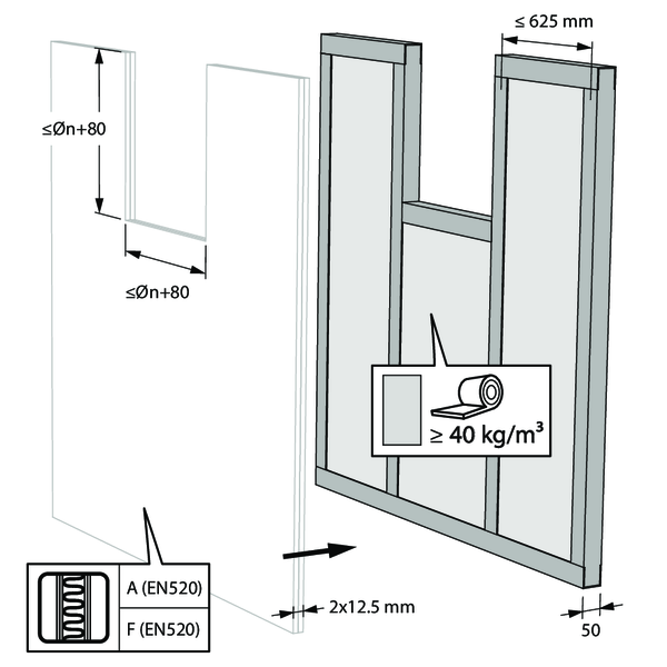
Installation in flexible wall (metal stud gypsum plasterboard wall)
The product was tested and approved in:
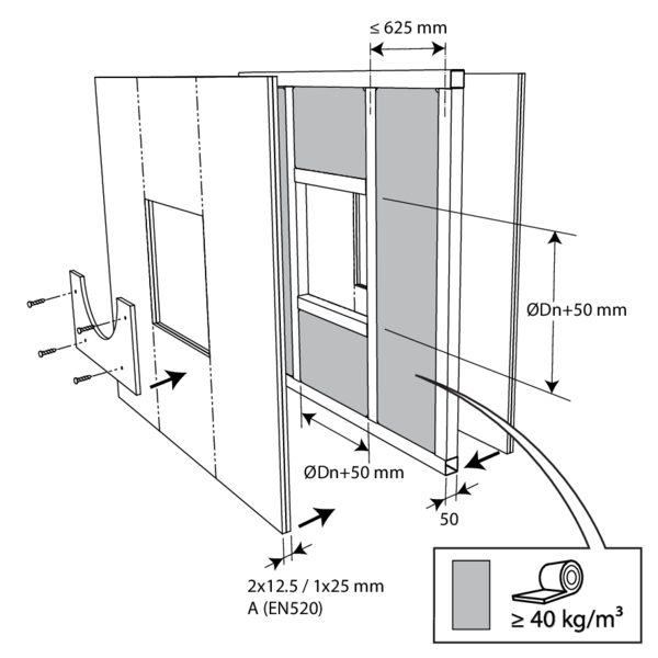
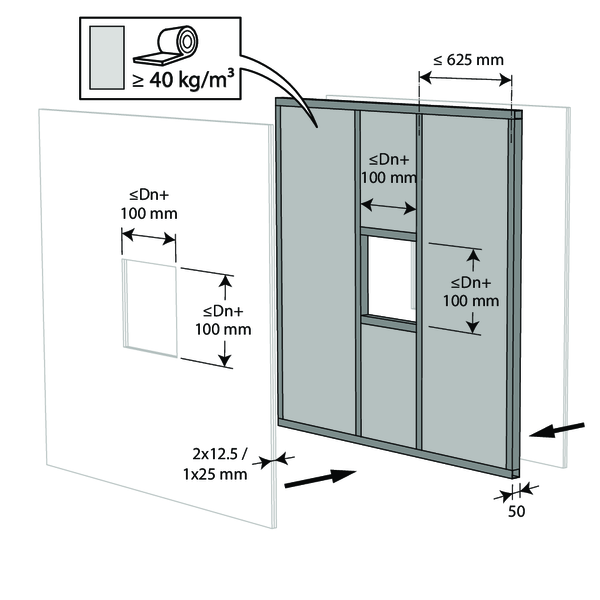
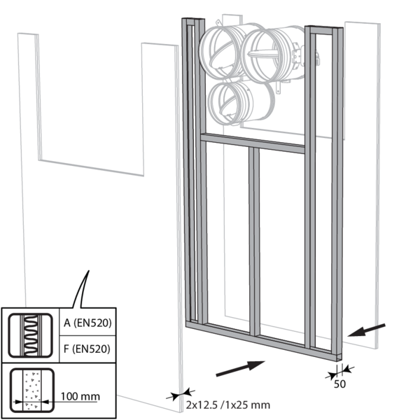
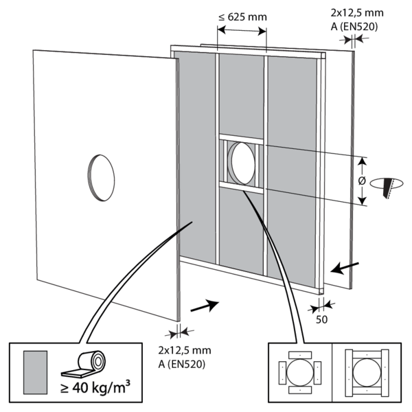
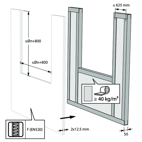
- Metal studs gypsum plasterboard Type A (EN 520) ≥ 100 mm | EI 60 (ve i o) S - (500 Pa) | Stone wool ≥ 40 kg/m³ + cover plates | Type of installation: built-in, 0-360°. Minimal distances authorised with axis till 45°. | Ø 100-250 mm
The dampers can be installed at a minimum distance (≥ 30 mm) from an adjacent wall or from another damper.
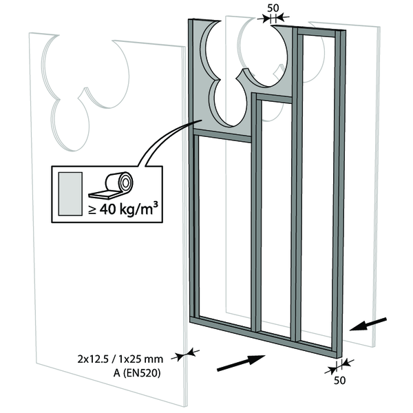
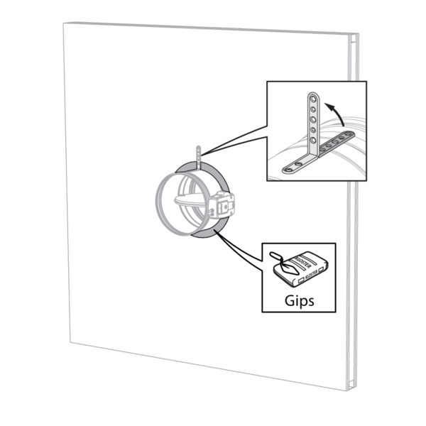
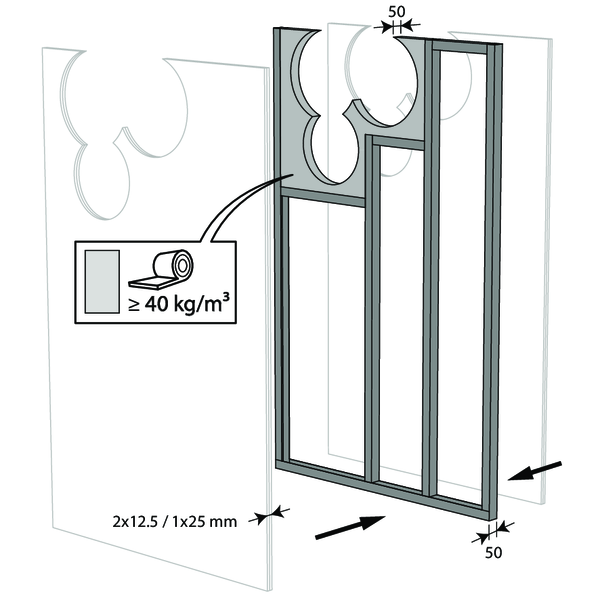
Build the drywall and foresee horizontal and vertical studs around the opening.
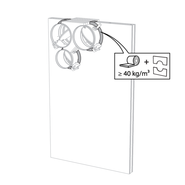
In the opening around the dampers (Dn + 50 mm), the void between the gypsum boards is filled with stone wool with a minimum density of 40 kg/m³.
In the opening around the dampers (Dn + 50 mm), the void between the gypsum boards is filled with stone wool with a minimum density of 40 kg/m³.

Mount the dampers in the opening.
Apply rigid stone wool panels (≥ 150 kg/m³) to a depth of 400 mm (150 mm on the mechanism side of the wall) to seal the opening at the side with minimal distances.
The surface of this sealing is set between the axes (centres) of the dampers.
Caution: the opening is sealed according to the existing classification (see next point) when: - 2 fire dampers are installed at a minimum distance from one another but at a normal distance (≥ 75 mm) from the wall or floor/ceiling. - One single (no cluster) fire damper is located at a minimum distance (≤ 75 mm) from a wall or floor/ceiling.
Seal the rest of the opening with standard stone wool 40 kg/m³ across the entire wall thickness.
Apply cover plates (gypsum plasterboards) to finish the surface at both sides.
Seal off the space between the plasterboards with jointfiller.
Seal off the space between the plasterboards with jointfiller.
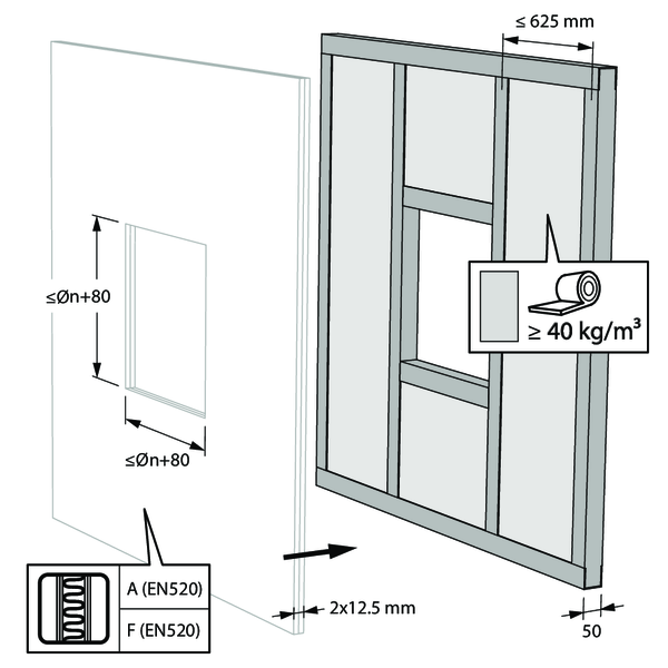
Installation in flexible wall (metal stud gypsum plasterboard wall), sealing with gypsum
The product was tested and approved in:
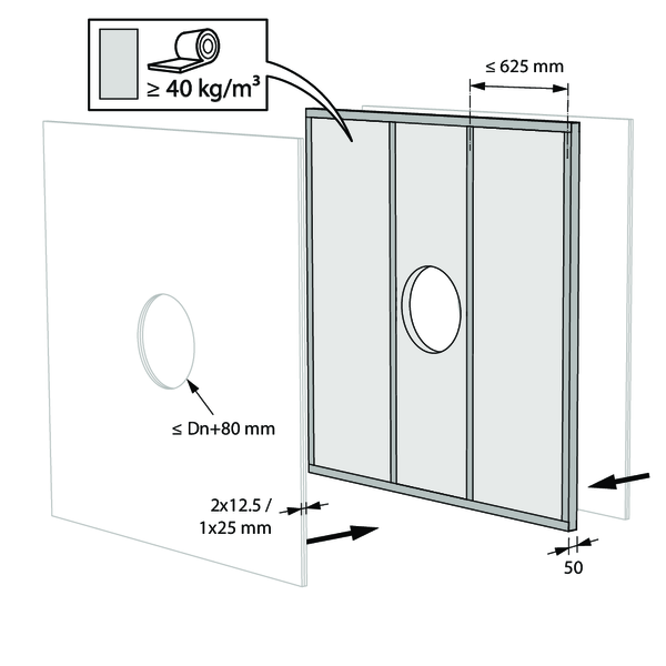
- Metal studs gypsum plasterboard Type A (EN 520) ≥ 100 mm | EI 60 (ve i o) S - (500 Pa) | Gypsum | Type of installation: built-in, 0-360°. Minimal distances authorised with axis till 45°. | Ø 100-315 mm
- Metal studs gypsum plasterboard Type F (EN 520) ≥ 100 mm | EI 90 (ve i o) S - (500 Pa) | Gypsum | Type of installation: built-in, 0-360°. Minimal distances authorised with axis till 45°. | Ø 100-315 mm

The dampers can be installed at a minimum distance (≥ 30 mm) from an adjacent wall or from another damper.
Build the drywall and foresee horizontal and vertical studs around the opening.
In the opening around the dampers, the void between the gypsum boards is partially filled (up to Dn + 40 mm) with stone wool with a minimum density of 40 kg/m³.
In the opening around the dampers, the void between the gypsum boards is partially filled (up to Dn + 40 mm) with stone wool with a minimum density of 40 kg/m³.

Mount the dampers in the opening.
Apply rigid stone wool panels (≥ 150 kg/m³) to a depth of 400 mm (150 mm on the mechanism side of the wall) to seal the opening at the side with minimal distances.
The surface of this sealing is set between the axes (centres) of the dampers.
Caution: the opening is sealed according to the existing classification (see next point) when: - 2 fire dampers are installed at a minimum distance from one another but at a normal distance (≥ 75 mm) from the wall or floor/ceiling. - One single (no cluster) fire damper is located at a minimum distance (≤ 75 mm) from a wall or floor/ceiling.
Apply rigid stone wool panels (≥ 150 kg/m³) to a depth of 400 mm (150 mm on the mechanism side of the wall) to seal the opening at the side with minimal distances.
The surface of this sealing is set between the axes (centres) of the dampers.
Caution: the opening is sealed according to the existing classification (see next point) when: - 2 fire dampers are installed at a minimum distance from one another but at a normal distance (≥ 75 mm) from the wall or floor/ceiling. - One single (no cluster) fire damper is located at a minimum distance (≤ 75 mm) from a wall or floor/ceiling.
Seal the rest of the opening with standard gypsum across the entire wall thickness.
Installation in flexible wall (metal stud gypsum plasterboard wall), sealing with mortar
The product was tested and approved in:
- Metal studs gypsum plasterboard Type F (EN 520) ≥ 100 mm | EI 90 (ve i o) S - (300 Pa) | Mortar | Type of installation: built-in, 0-360°. Minimal distances authorised with axis till 45°. | Ø 100-315 mm
The dampers can be installed at a minimum distance (≥ 30 mm) from an adjacent wall or from another damper.
Build the drywall and foresee horizontal and vertical studs around the opening.
For a circular wall opening, the space between the plasterboard sheets is partially (up to Dn + 40 mm) filled with stone wool with a minimum density of 40kg/m³.
For a circular wall opening, the space between the plasterboard sheets is partially (up to Dn + 40 mm) filled with stone wool with a minimum density of 40kg/m³.
Mount the dampers in the opening.
Apply rigid stone wool panels (≥ 150 kg/m³) to a depth of 400 mm (150 mm on the mechanism side of the wall) to seal the opening at the side with minimal distances.
The surface of this sealing is set between the axes (centres) of the dampers.
Caution: the opening is sealed according to the existing classification (see next point) when: - 2 fire dampers are installed at a minimum distance from one another but at a normal distance (≥ 75 mm) from the wall or floor/ceiling. - One single (no cluster) fire damper is located at a minimum distance (≤ 75 mm) from a wall or floor/ceiling.
Apply rigid stone wool panels (≥ 150 kg/m³) to a depth of 400 mm (150 mm on the mechanism side of the wall) to seal the opening at the side with minimal distances.
The surface of this sealing is set between the axes (centres) of the dampers.
Caution: the opening is sealed according to the existing classification (see next point) when: - 2 fire dampers are installed at a minimum distance from one another but at a normal distance (≥ 75 mm) from the wall or floor/ceiling. - One single (no cluster) fire damper is located at a minimum distance (≤ 75 mm) from a wall or floor/ceiling.
Seal the rest of the opening with standard mortar across the entire wall thickness.
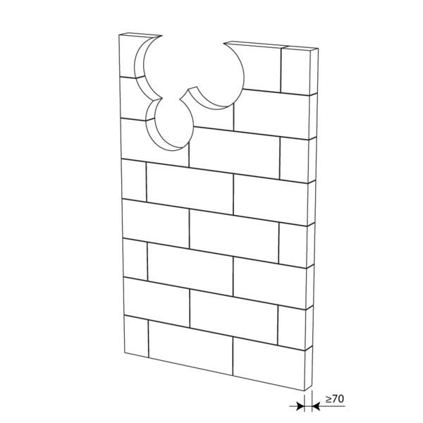
Installation in gypsum block wall
The product was tested and approved in:
- Gypsum blocks ≥ 70 mm | EI 90 (ve i o) S - (500 Pa) | Block glue | Type of installation: built-in, 0-360°. Minimal distances authorised with axis till 45°. | Ø 100-315 mm
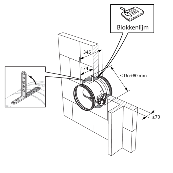
The dampers can be installed at a minimum distance from an adjacent wall or from another damper.
Make the necessary openings (≤ Dn + 80 mm) in the wall.
Mount the dampers in the opening.
Apply rigid stone wool panels (≥ 150 kg/m³) to a depth of 400 mm (150 mm on the mechanism side of the wall) to seal the opening at the side with minimal distances.
The surface of this sealing is set between the axes (centres) of the dampers.
Caution: the opening is sealed according to the existing classification (see next point) when: - 2 fire dampers are installed at a minimum distance from one another but at a normal distance (≥ 75 mm) from the wall or floor/ceiling. - One single (no cluster) fire damper is located at a minimum distance (≤ 75 mm) from a wall or floor/ceiling.
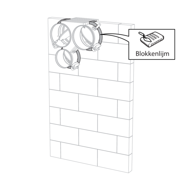
Seal the rest of the opening with block glue across the entire wall thickness.
Installation in flexible and rigid wall, sealing with rigid rock wool boards with coating
The product was tested and approved in:
- Aerated concrete ≥ 100 mm | EI 90 (ve i o) S - (300 Pa) | Stone wool + coating ≥ 140 kg/m³ | CR60 | Type of installation: built-in, 0-360°. Minimal distances authorised with axis till 45°. | Ø 100-315 mm
- Metal studs gypsum plasterboard Type A (EN 520) ≥ 100 mm | EI 60 (ve i o) S - (300 Pa) | Stone wool + coating ≥ 140 kg/m³ | CR60 | Type of installation: built-in, 0-360°. Minimal distances authorised with axis till 45°. | Ø 100-315 mm
- Metal studs gypsum plasterboard Type F (EN 520) ≥ 100 mm | EI 90 (ve i o) S - (300 Pa) | Stone wool + coating ≥ 140 kg/m³ | CR60 | Type of installation: built-in, 0-360°. Minimal distances authorised with axis till 45°. | Ø 100-315 mm
- Aerated concrete ≥ 100 mm | EI 60 (ve i o) S - (300 Pa) | Stone wool Mulcol Multimastic FB1 + coating | Type of installation: built-in, 0-360°. Minimal distances authorised with axis till 45°. | Ø 100-315 mm
- Metal studs gypsum plasterboard Type F (EN 520) ≥ 100 mm | EI 60 (ve i o) S - (300 Pa) | Stone wool Mulcol Multimastic FB1 + coating | Type of installation: built-in, 0-360°. Minimal distances authorised with axis till 45°. | Ø 100-315 mm
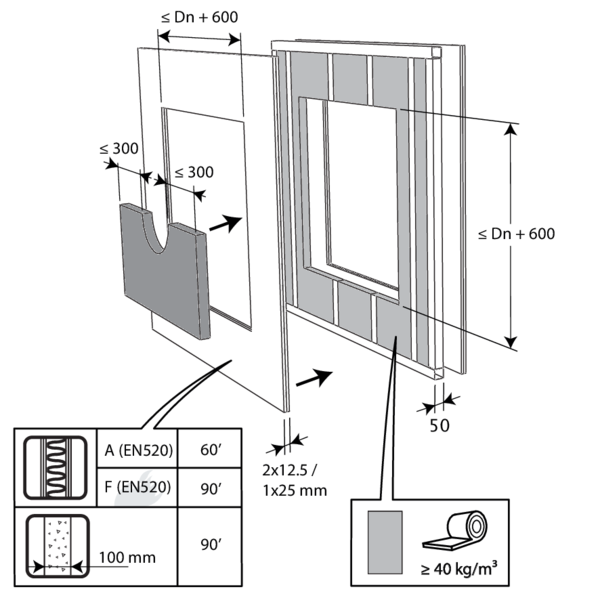
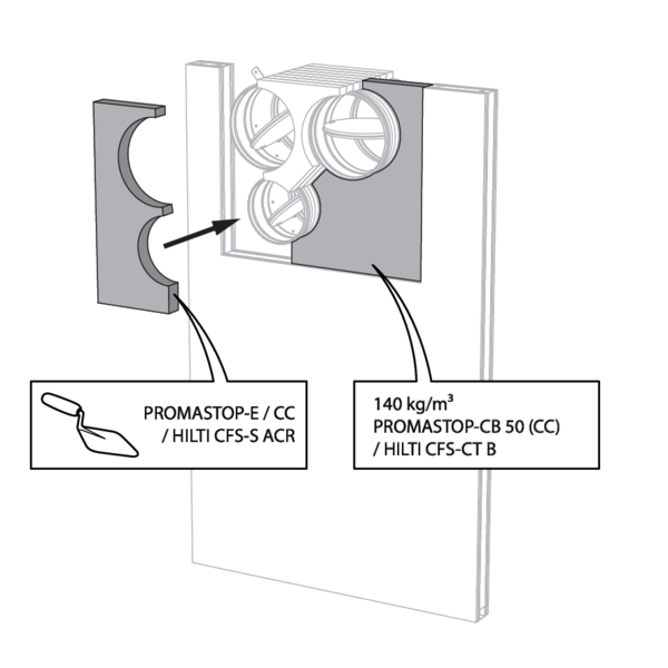
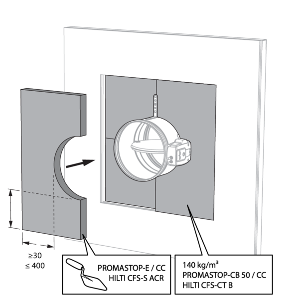
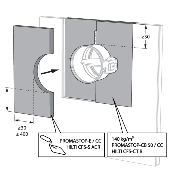
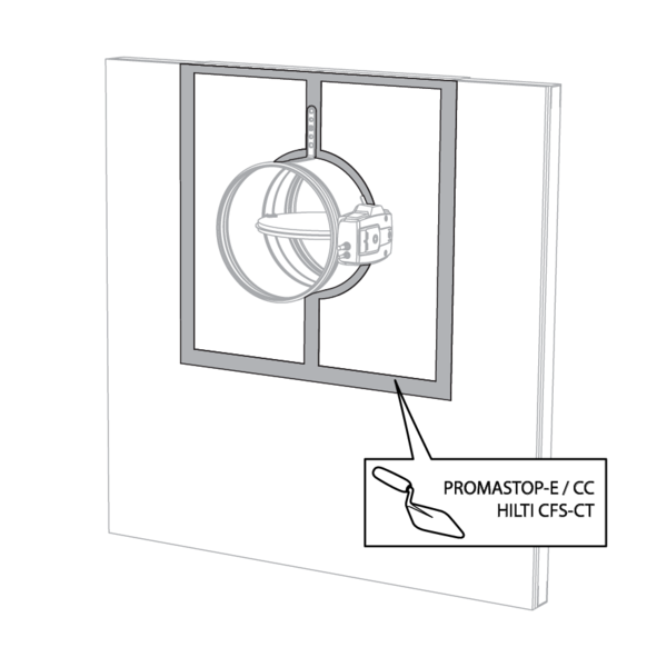
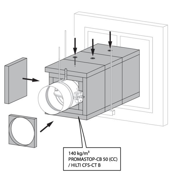
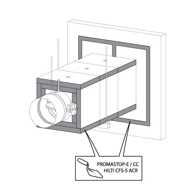
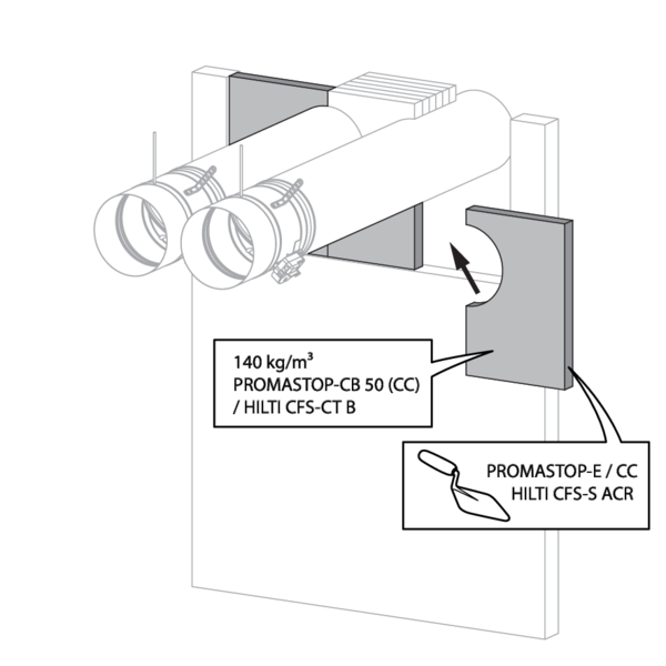
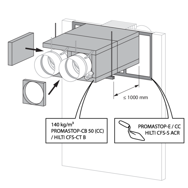
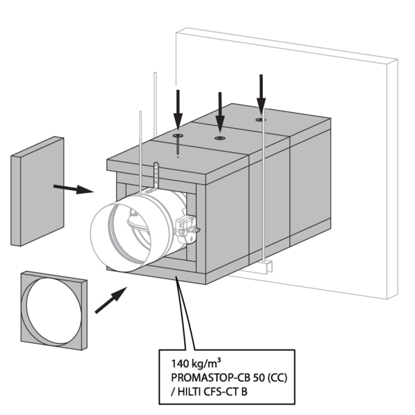
The opening around the damper is sealed with 2 layers of 50 mm-thick mineral wool panels with fire resistant coating on one side (type PROMASTOP-CB 50 / PROMASTOP-CB/CC 50 / HILTI CFS-CT B / Mulcol Multimastic FB1 / PYRO-SAFE® MFP).
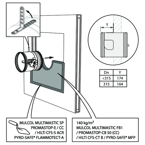
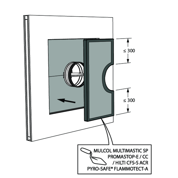
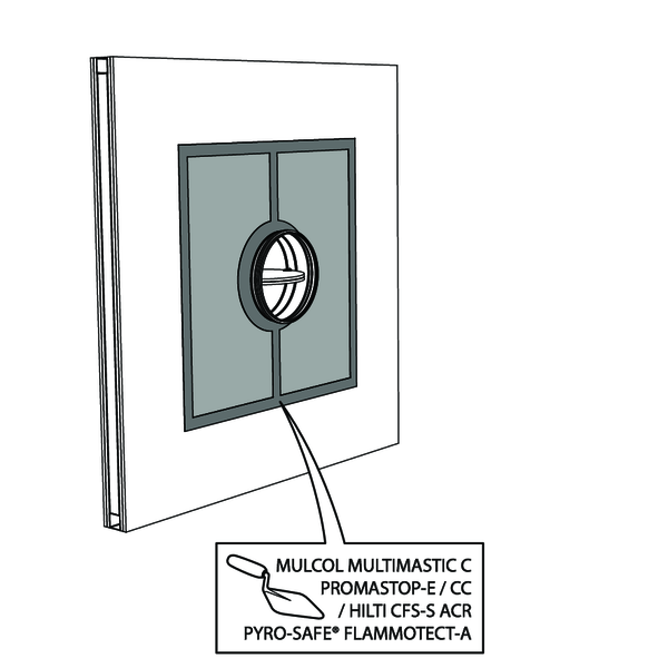
The joints on these 2 layers must be installed staggered and covered all around the edge with coating (type PROMASTOP-E / PROMASTOP-CC / HILTI CFS-S-ACR / Mulcol Multimastic SP / PYRO-SAFE® FLAMMOTECT-A).
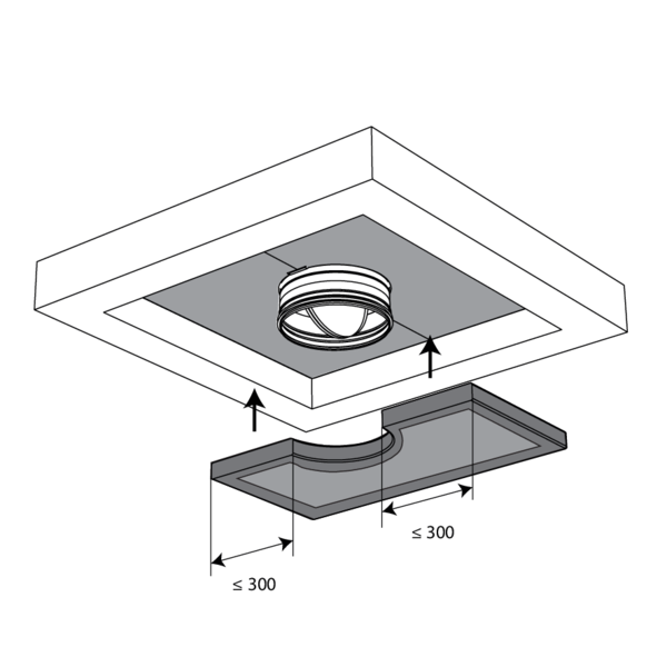
The damper does not need to be centered in the opening (with max dimensions fire damper + 600 mm). The maximal distance between the damper and the edge of the opening is 400 mm.
The dampers can be installed at a minimum distance (≥ 30 mm) from an adjacent wall or from another damper.
Build the drywall and foresee horizontal and vertical studs around the opening.
Mount the dampers in the opening.
Mount the dampers in the opening.
Apply rigid stone wool panels (≥ 150 kg/m³) to a depth of 400 mm (150 mm on the mechanism side of the wall) to seal the opening at the side with minimal distances.
The surface of this sealing is set between the axes (centres) of the dampers.
Caution: the opening is sealed according to the existing classification (see next point) when: - 2 fire dampers are installed at a minimum distance from one another but at a normal distance (≥ 75 mm) from the wall or floor/ceiling. - One single (no cluster) fire damper is located at a minimum distance (≤ 75 mm) from a wall or floor/ceiling.
Seal the rest of the opening with 2 layers of 50 mm-thick coated rigid mineral wool panels (see above).
Installation in rigid floor, sealing with rigid rock wool boards with coating
The product was tested and approved in:
- Aerated concrete ≥ 150 mm | EI 90 (ho i o) S - (300 Pa) | Stone wool + coating ≥ 140 kg/m³ | CR60 | Type of installation: built-in, 0-360°. Minimal distances authorised. | Ø 100-315 mm
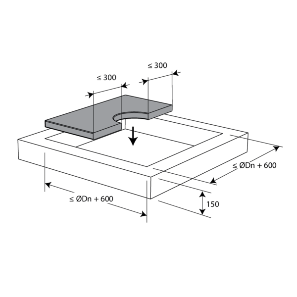
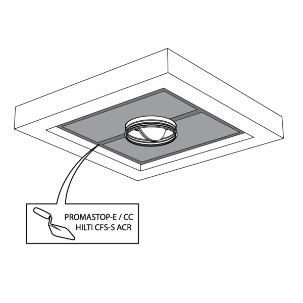
The opening around the damper is sealed with 2 layers of 50 mm-thick mineral wool panels with fire resistant coating on one side (type PROMASTOP-CB 50 / PROMASTOP-CB/CC 50 / HILTI CFS-CT B).
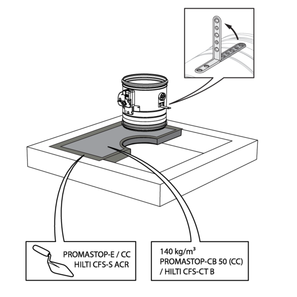
The joints on these 2 layers must be installed staggered and covered all around the edge with coating (type PROMASTOP-E / PROMASTOP-CC / HILTI CFS-S-ACR).
The damper does not need to be centered in the opening (with max dimensions fire damper + 600 mm). The maximal distance between the damper and the edge of the opening is 400 mm.
The dampers can be installed at a minimum distance (≥ 30 mm) from an adjacent wall or from another damper.
For details, please refer to 'Installation in flexible and rigid wall, sealing with rigid rock wool boards with coating'
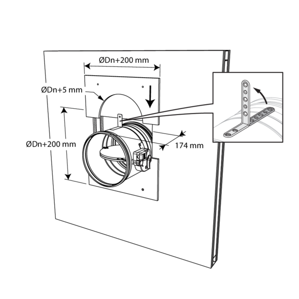
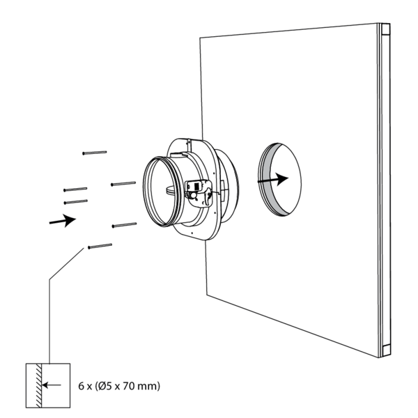
Installation in rigid wall and floor with collar for surface-mount 1s
The product was tested and approved in:
- Aerated concrete Not applicable EI 60 (ve i n o) S - (500 Pa) Rigid wall Aerated concrete ≥ 100 mm | EI 60 (ve i o) S - (500 Pa) | Not applicable | CR60 | Type of installation: surface-mounted, 0/180° (500 Pa), 0-360° (300 Pa). Minimal distances authorised with axis till 45°. | CR60-1S Ø 100-315 mm
- Aerated concrete Not applicable EI 60 (ho i n o) S - (500 Pa) Rigid floor Aerated concrete ≥ 100 mm | EI 60 (ho i o) S - (500 Pa) | Not applicable | CR60 | Type of installation: surface-mounted, 0/180° (500 Pa), 0-360° (300 Pa). Minimal distances authorised with axis till 45°. | CR60-1S Ø 100-315 mm
- Aerated concrete Not applicable EI 90 (ho i g o) S - (500 Pa) Rigid floor Aerated concrete ≥ 100 mm | EI 90 (ho i o) S - (500 Pa) | Not applicable | CR60 | Type of installation: surface-mounted, 0/180° (500 Pa), 0-360° (300 Pa). Minimal distances authorised with axis till 45°. | CR60-1S Ø 100-315 mm
The dampers can be installed at a minimum distance from an adjacent wall or from another damper.
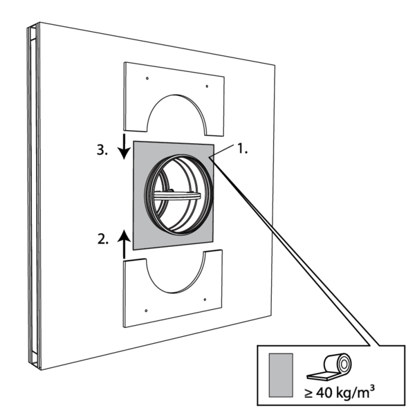
Installation in flexible wall with collar for surface-mount 1s
The product was tested and approved in:
- Metal studs gypsum plasterboard Type A (EN 520) Not applicable EI 60 (ve i n o) S - (500 Pa) Flexible wall Metal studs gypsum plasterboard Type A (EN 520) ≥ 100 - ≤ 125 mm | EI 60 (ve i o) S - (500 Pa) | Not applicable | CR60 | Type of installation: surface-mounted, 0/180° (500 Pa), 0-360° (300 Pa). Minimal distances authorised with axis till 45°. | CR60-1S Ø 100-315 mm
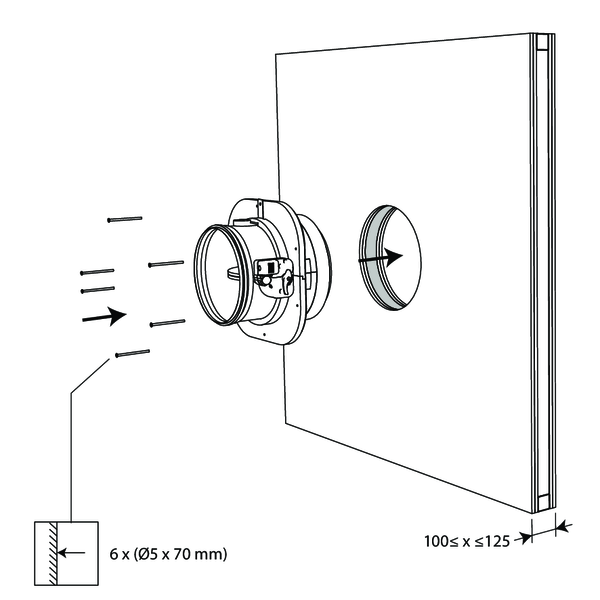
The dampers can be installed at a minimum distance from an adjacent wall or from another damper.
Installation in shaft wall with collar for surface-mount 1s
The product was tested and approved in:
- Metal studs gypsum plasterboard Type F (EN 520) Not applicable EI 60 (ve i n o) S - (500 Pa) Asymmetrical flexible wall (shaft wall) Metal studs gypsum plasterboard Type F (EN 520) ≥ 80 mm | EI 60 (ve i o) S - (500 Pa) | Not applicable | CR60 | Type of installation: surface-mounted, 0/180° (500 Pa), 0-360° (300 Pa). Minimal distances authorised with axis till 45°. | CR60-1S Ø 100-315 mm
The dampers can be installed at a minimum distance from an adjacent wall or from another damper.
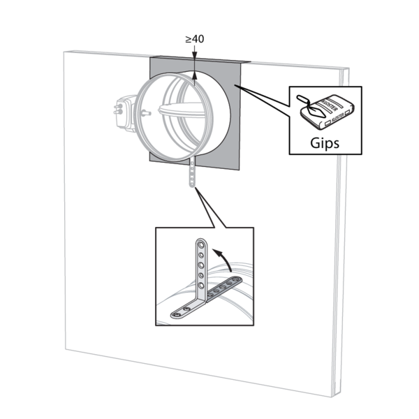
Installation in shaft wall, sealing with gypsum
The product was tested and approved in:
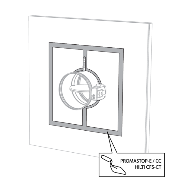
- Metal studs gypsum plasterboard Type A (EN 520) ≥ 75 mm | EI 30 (ve i o) S - (500 Pa) | Gypsum | Type of installation: built-in 0/180°. Minimal distances authorised. | Ø 100-315 mm
The dampers can be installed at a minimum distance (≥ 40 mm) from a ceiling or floor slab.
Installation in shaft wall, sealing with rigid rock wool boards with coating
The product was tested and approved in:
- Metal studs gypsum plasterboard Type F (EN 520) ≥ 75 mm | EI 30 (ve i o) S - (300 Pa) | Stone wool + coating ≥ 140 kg/m³ | Type of installation: built-in 0/180°. Minimal distances authorised. | Ø 100-315 mm
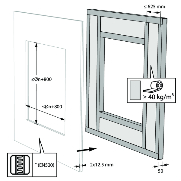
The opening around the damper is sealed with 2 hard rock wool slabs of 50 mm. These boards should be placed in a slanted position and the joints should be covered all around with filling paste.
The damper does not need to be centered in the opening (with max dimensions Ø fire damper + 800 mm). The maximal distance between the damper and the edge of the opening is 400 mm.
The dampers can be installed at a minimum distance (≥ 30 mm) from a ceiling or floor slab.
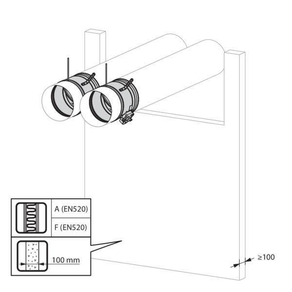
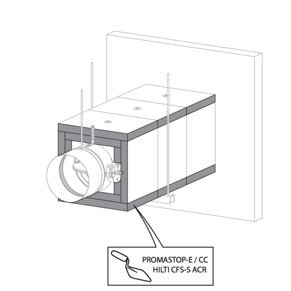
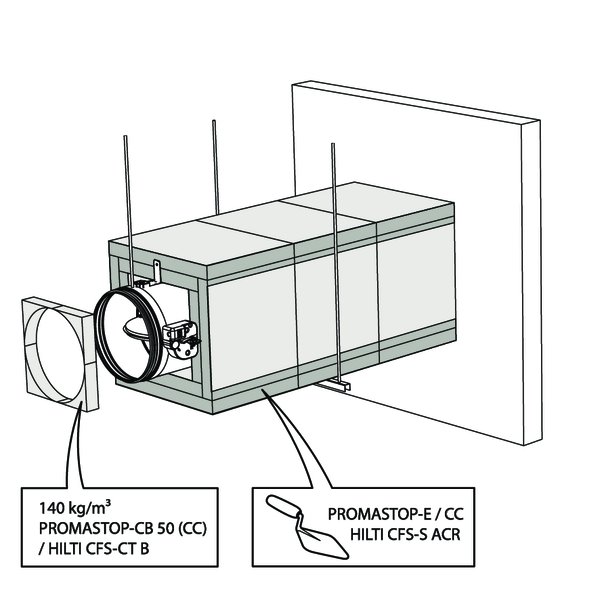
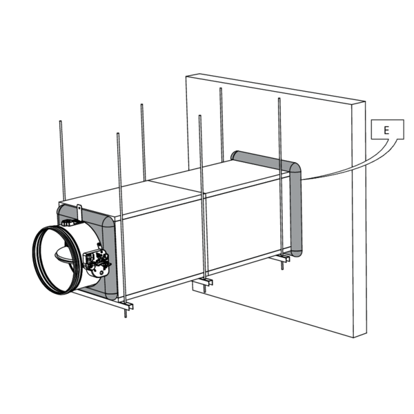
Installation remote from the wall, sealing and insulation with rigid rock wool boards with coating
The product was tested and approved in:
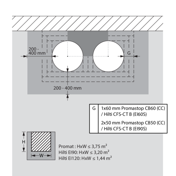
- Aerated concrete ≥ 100 mm | EI 60 (ve i o) S - (300 Pa) | Galvanised duct + stone wool + coating ≥ 140 kg/m³ 1x60 mm | CR60 | Type of installation: remote from the wall, 0/180°. Minimal distances authorised. | Ø 100-315 mm
- Aerated concrete ≥ 100 mm | EI 90 (ve i o) S - (300 Pa) | Galvanised duct + stone wool + coating ≥ 140 kg/m³ 2x50 mm | CR60 | Type of installation: remote from the wall, 0/180°. Minimal distances authorised. | Ø 100-315 mm
- Metal studs gypsum plasterboard Type F (EN 520) ≥ 100 mm | EI 90 (ve i o) S - (300 Pa) | Galvanised duct + stone wool + coating ≥ 140 kg/m³ 2x50 mm | CR60 | Type of installation: remote from the wall, 0/180°. Minimal distances authorised. | Ø 100-315 mm
- Metal studs gypsum plasterboard Type A (EN 520) ≥ 100 mm | EI 60 (ve i o) S - (300 Pa) | Galvanised duct + stone wool + coating ≥ 140 kg/m³ 1x60 mm | CR60 | Type of installation: remote from the wall, 0/180°. Minimal distances authorised. | Ø 100-315 mm
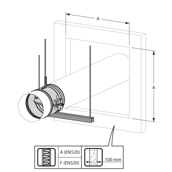
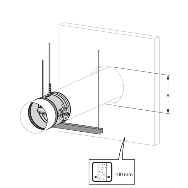
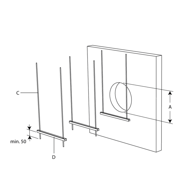
An opening with maximal dimensions “A” is made in the wall.
For a light partition wall, follow the wall assembly under “Installation in flexible or rigid wall - Sealing with fire resistant rigid panels of mineral wool“.
For a light partition wall, follow the wall assembly under “Installation in flexible or rigid wall - Sealing with fire resistant rigid panels of mineral wool“.
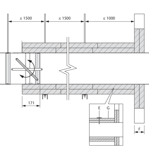
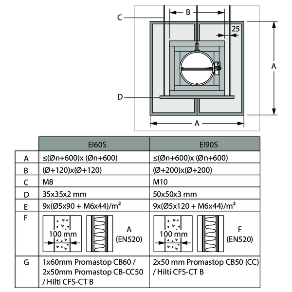
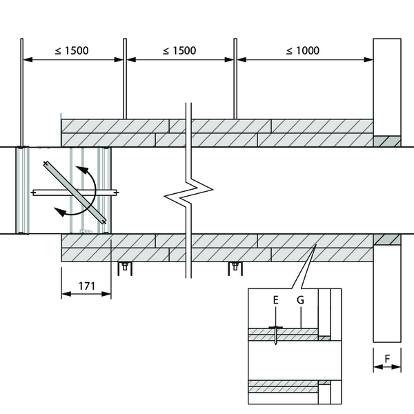
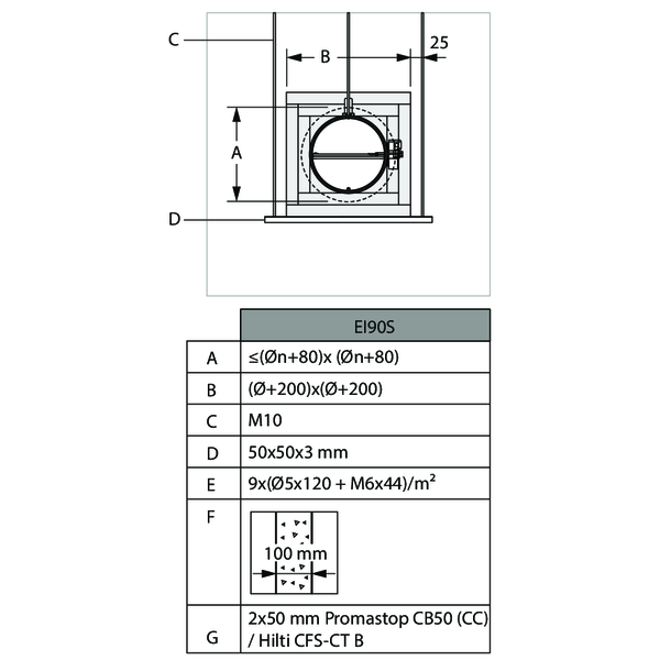
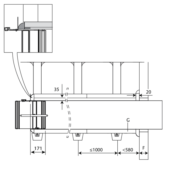
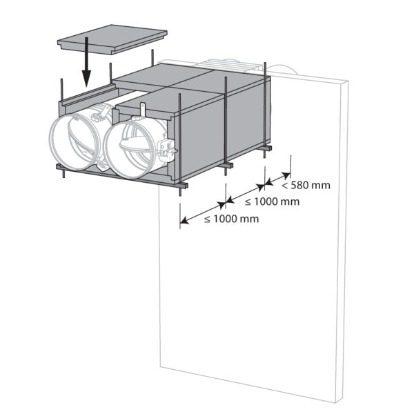
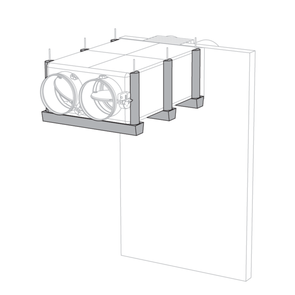
The fire damper is mounted remote from the wall at the end of a metal duct. The fire damper is supported by a clamping ring of the same diameter as the damper, held in place by threaded rods “C”. The duct is supported every 1500 mm.
The suspensions consist of threaded rods “C” and U-shaped steel profiles “D”. A free space of maximum 25 mm is left between the threaded rods and the vertical walls of the stone wool casing “B”.
The suspensions consist of threaded rods “C” and U-shaped steel profiles “D”. A free space of maximum 25 mm is left between the threaded rods and the vertical walls of the stone wool casing “B”.
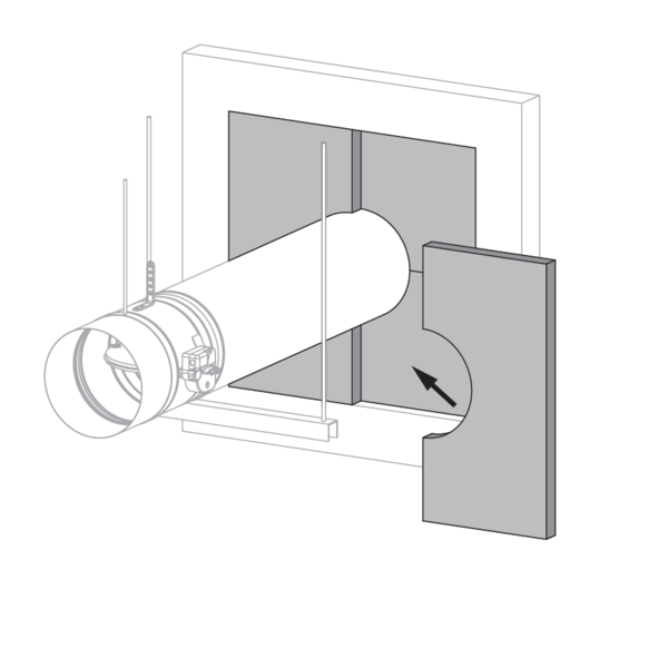
The opening around the duct is sealed with stone wool plates type Promastop CB(/CC) / Hilti CFS-CT B (“G”). The edges are sealed and maintained in place with PROMASTOP E / PROMASTOP CC / HILTI CFS-S ACR coating.
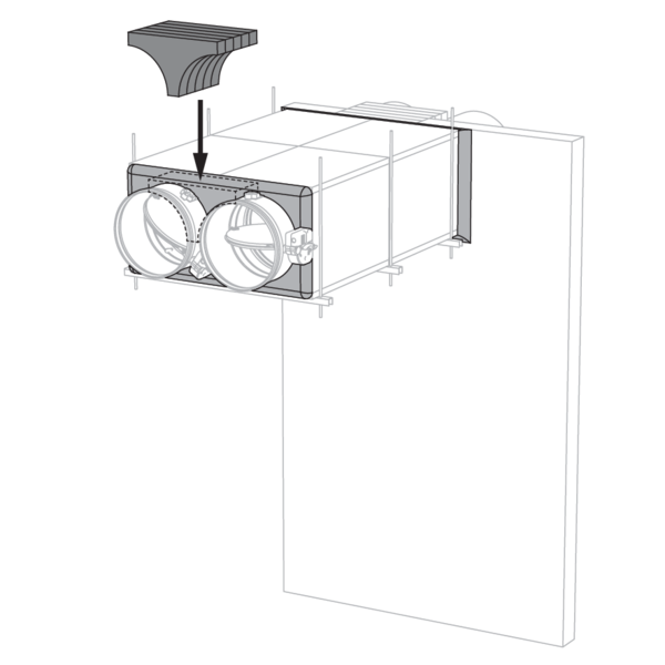
The duct is covered over its entire length with stone wool plates “G”. To adhere to the duct, the plates are completely coated on one side with fire resitant coating and affixed to the duct with steel screws and washers “E”.
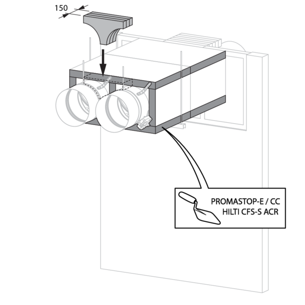
The damper casing is covered with stone wool plates “G” for 171 mm. A free space should be left around the mechanism to guarantee access.
The joints between the plates, between the wall and the plates as well as the screws and washers are filled with coating PROMASTOP E / PROMASTOP CC / HILTI CFS-S ACR.
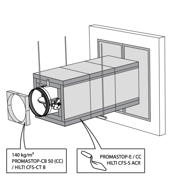
An additional stone wool panel type “G”, coated with PROMASTOP E / PROMASTOP CC / HILTI CFS-S ACR, is applied in the opening between the damper casing and the stone wool panels.
The dampers can be installed at a minimum distance from an adjacent wall or from another damper.
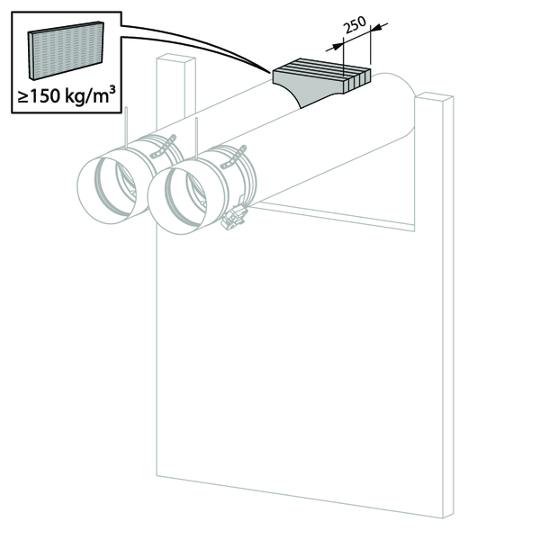
Apply rigid stone wool panels (150 kg/m³) to a depth of 250 mm (wall thickness + additional at the rear side of the wall) to seal the opening at the side with minimal distances.
When the distance between the damper and the wall is greater than 75 mm, the sealing of the opening between the damper and the wall is carried out according to the pre-existing classification.
When the distance between the damper and the wall is greater than 75 mm, the sealing of the opening between the damper and the wall is carried out according to the pre-existing classification.
Apply rigid stone wool panels (150 kg/m³) to a depth of 150 mm to seal the opening at the side with minimal distances.
Installation remote from the wall, sealing with mortar and insulation with rigid rock wool boards with coating
The product was tested and approved in:
- Aerated concrete ≥ 100 mm | EI 90 (ve i o) S - (300 Pa) | Galvanised duct + stone wool + coating ≥ 140 kg/m³ 2x50 mm + mortar | Type of installation: remote from the wall, 0/180°. Minimal distances authorised. | Ø 100-315 mm
An opening with maximal dimensions “A” is made in the wall.
The fire damper is mounted remote from the wall at the end of a metal duct. The fire damper is supported by a clamping ring of the same diameter as the damper, held in place by threaded rods “C”. The duct is supported every 1500 mm.
The suspensions consist of threaded rods “C” and U-shaped steel profiles “D”. A free space of maximum 25 mm is left between the threaded rods and the vertical walls of the stone wool casing “B”.
The suspensions consist of threaded rods “C” and U-shaped steel profiles “D”. A free space of maximum 25 mm is left between the threaded rods and the vertical walls of the stone wool casing “B”.
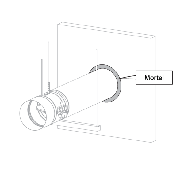
The opening around the duct is sealed with standard mortar.
The duct is covered over its entire length with stone wool plates “G”. To adhere to the duct, the plates are completely coated on one side with fire resitant coating and affixed to the duct with steel screws and washers “E”.
The damper casing is covered with stone wool plates “G” for 171 mm. A free space should be left around the mechanism to guarantee access.
The joints between the plates, between the wall and the plates as well as the screws and washers are filled with coating PROMASTOP E / PROMASTOP CC / HILTI CFS-S ACR.
An additional stone wool panel type “G”, coated with PROMASTOP E / PROMASTOP CC / HILTI CFS-S ACR, is applied in the opening between the damper casing and the stone wool panels.
Installation remote from the wall + GEOFLAM
The product was tested and approved in:
- Aerated concrete ≥ 100 mm | EI 90 (ve i o) S - (500 Pa) | Galvanised duct + GEOFLAM® F 45 mm + mortar | Type of installation: remote from the wall, 0/180°. Minimal distances authorised. | Ø 100-315 mm
- Aerated concrete ≥ 100 mm | EI 90 (ve i o) S - (500 Pa) | Galvanised duct + GEOFLAM® Light 35 mm + mortar | Type of installation: remote from the wall, 0/180°. Minimal distances authorised. | Ø 100-315 mm
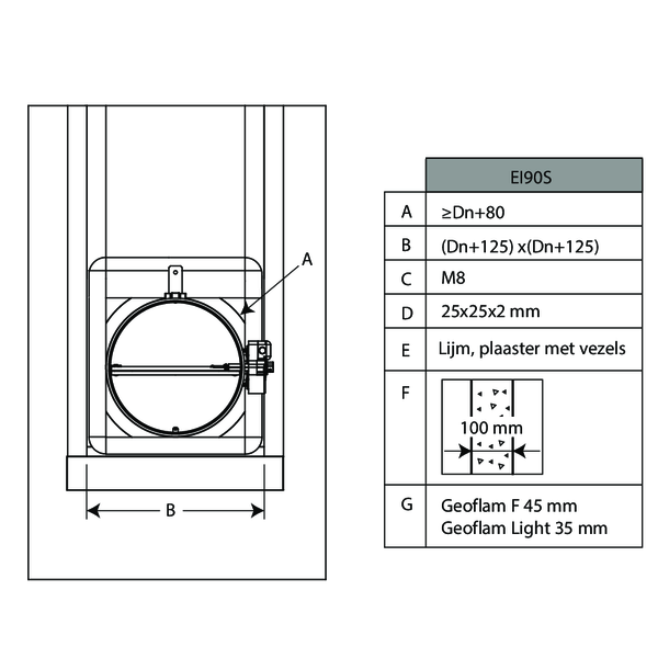
An opening with maximal dimensions “A” is made in the wall.
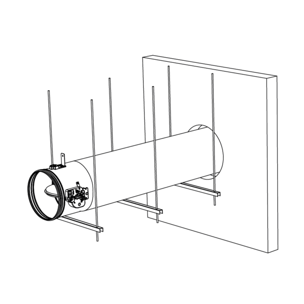
The fire damper is mounted remote from the wall at the end of a metal duct. The duct is supported every 1000 mm.
The suspensions consist of threaded rods “C” and U-shaped steel profiles “D”. A free space of maximum 25 mm is left between the threaded rods and the vertical walls of the casing “B”.
The suspensions consist of threaded rods “C” and U-shaped steel profiles “D”. A free space of maximum 25 mm is left between the threaded rods and the vertical walls of the casing “B”.
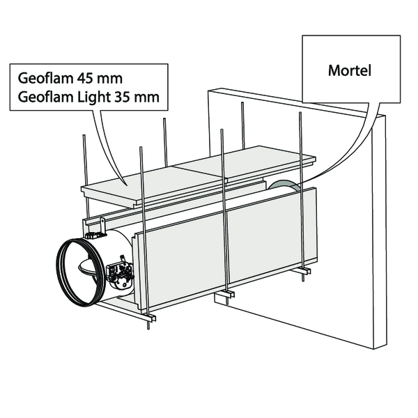
The opening around the duct is sealed with standard mortar. The duct is covered with 45 mm thick GEOFLAM F plates or 35 mm thick GEOFLAM Light plates "G”.
The plates adhere to each other with glue and fibrous plaster “E”. The damper casing is also covered on a length of 171 mm.
The plates adhere to each other with glue and fibrous plaster “E”. The damper casing is also covered on a length of 171 mm.
The GEOFLAM F / GEOFLAM Light plates stop at a distance of 20 mm from the wall. The free space is filled with fibrous plaster.
The same filling is applied to seal off the connection between the GEOFLAM F plates and the damper casing.
The same filling is applied to seal off the connection between the GEOFLAM F plates and the damper casing.
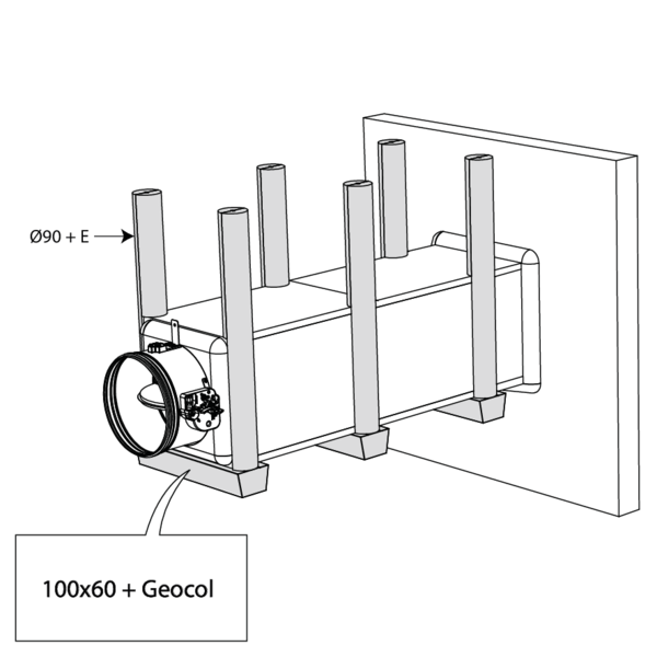
The threaded rods are covered with U-shaped plates of GEOFLAM (Ø 90 mm) and affixed with glue and fibrous plaster.
The profiles are covered with U-shaped shells GEOFLAM 100 x 60 mm, which are affixed to the underside of the shaft with GEOCOL (GEOSTAFF) cement plaster.
The profiles are covered with U-shaped shells GEOFLAM 100 x 60 mm, which are affixed to the underside of the shaft with GEOCOL (GEOSTAFF) cement plaster.
The dampers can be installed at a minimum distance from an adjacent wall or from another damper.
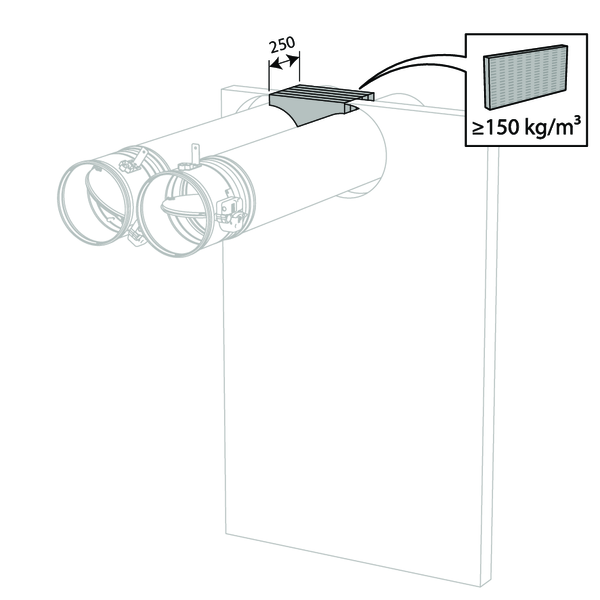
Apply rigid stone wool panels (150 kg/m³) to a depth of 250 mm (wall thickness + additional at the rear side of the wall) to seal the opening at the side with minimal distances.
Apply rigid stone wool panels (150 kg/m³) to a depth of 150 mm to seal the opening at the side with minimal distances.
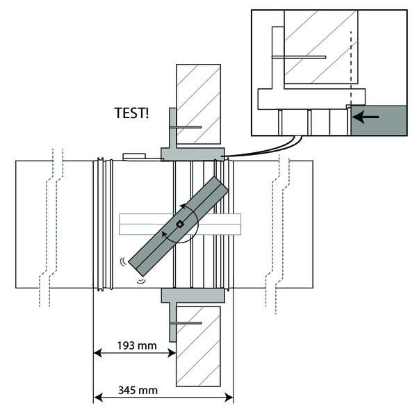
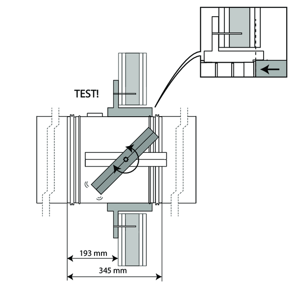
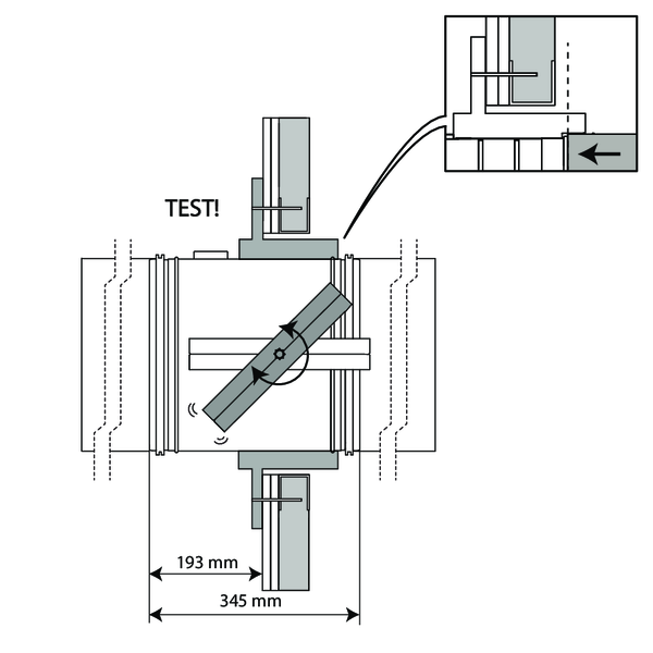
Inspection of the damper
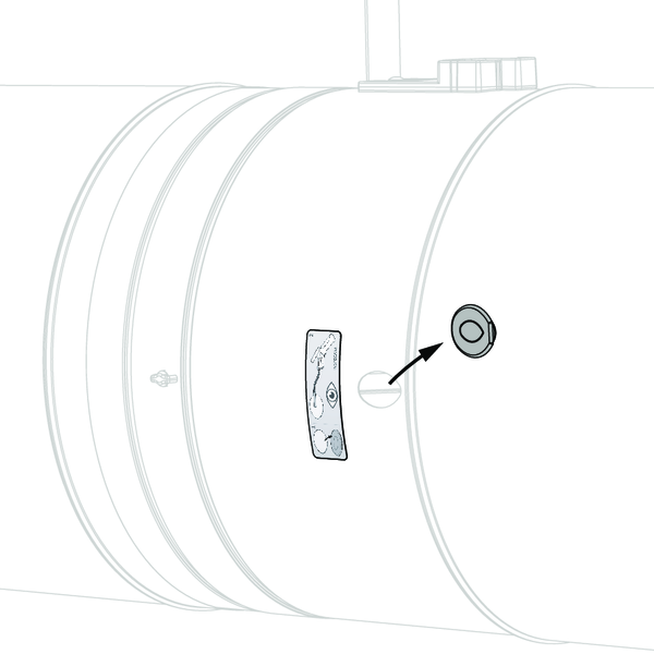
Remove the air-tight plug from the damper.
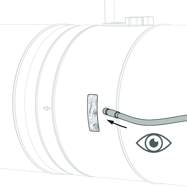
Insert the camera of the endoscope (for example Inspecam Rf-t) through the opening and inspect the inside of the damper.
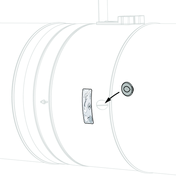
After inspection, replace the air-tight plug thoroughly on the damper opening. The position is crucial in order to maintain the air-tightness of the fire damper.
General remarks
- The installation must comply with the installation manual and the classification report.
- Axis orientation: see the declaration of performance.
- Avoid obstruction of adjoining ducts.
- Product installation: always with closed damper blade.
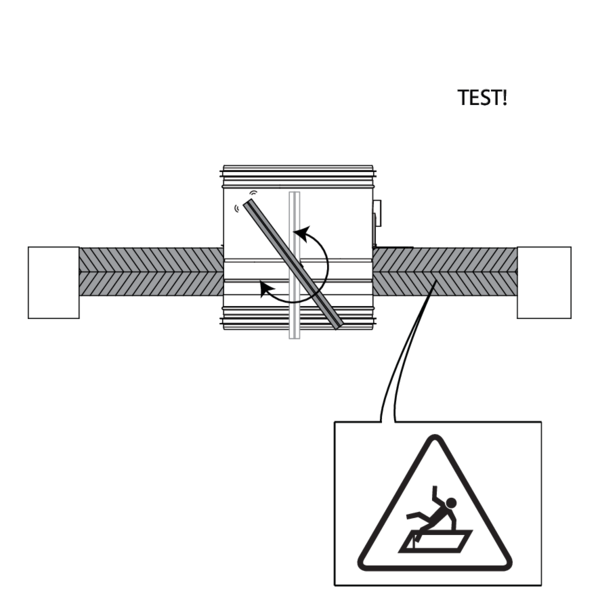
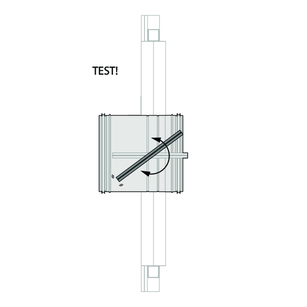
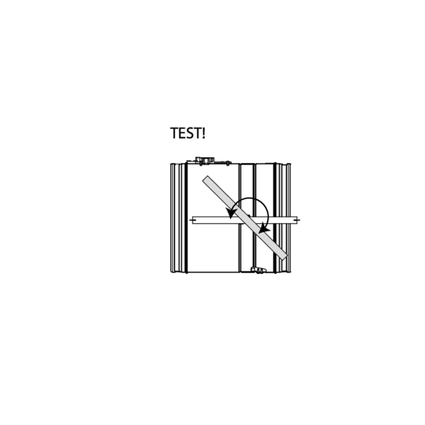
- Verify if the blade can move freely.
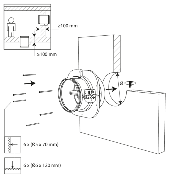
- Please observe safety distances with respect to other construction elements. The operating mechanism must also remain accessible: allow for a clearance of 200 mm around the housing.
- The air tightness class will be maintained if the damper is installed according to the installation manual.
- Rf-t fire dampers are always tested in standardised constructions according to EN 1366-2. The achieved results are valid for similar supporting constructions with a fire resistance, thickness and density equal or superior to the supporting construction used during the test.
- If the wall thickness exceeds the minimum thickness specified in our installation instructions, the following conditions apply to the sealing depth: - For flexible walls and sandwich panel system walls, the seal must always be applied over the full depth of the wall. - With rigid walls, rigid floors and plaster block walls, the minimum sealing depth as indicated in our installation instructions (often equal to the minimum wall thickness) is sufficient. Apply the seal at the height of the damper blade (from the wall limit indication).
- When installing a fire damper in a flexible metal stud wall, some installation methods do not require reinforcing profiles around the wall opening from a fire protection point of view (see below). Always follow the general instructions of the manufacturer of these wall systems when building this type of wall.
- The damper must remain accessible for inspection and maintenance.
- Schedule at least 2 visual checks each year.