CU-LT-1S - Installation
Position of the thermo-electric fuse (spring-return actuator BFLT)
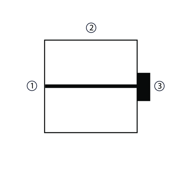
Position of the thermo-electric fuse on the damper casing: 1. on opposite side of mechanism if H < 250 mm and W < 250 mm; 2. on top if H < 250 mm and W ≥ 250 mm; 3. on mechanism side if H ≥ 250 mm.
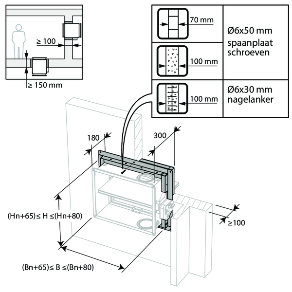
Installation at a minimal distance from another damper or from an adjacent supporting construction
Principle
According to the European test standard, a fire damper must be installed at a minimum distance of 75 mm from an adjacent wall and 200 mm from another damper, unless the solution was tested at a shorter distance.
According to the European test standard, a fire damper must be installed at a minimum distance of 75 mm from an adjacent wall and 200 mm from another damper, unless the solution was tested at a shorter distance.
Installation in rigid wall and floor as well as in gypsum block wall
The product was tested and approved in:
- Aerated concrete ≥ 100 mm | EI 120 (ve i o) S - (500 Pa) | Not applicable | Type of installation: surface-mounted, 0/90/180/270° | 200x100 mm ≤ CU-LT-1s ≤ 800x600 mm
- Aerated concrete ≥ 150 mm | EI 120 (ho i o) S - (500 Pa) | Not applicable | Type of installation: surface-mounted, 0/90/180/270° | 200x100 mm ≤ CU-LT-1s ≤ 800x600 mm
- Gypsum blocks ≥ 70 mm | EI 120 (ve i o) S - (500 Pa) | Not applicable | Type of installation: surface-mounted, 0/90/180/270° | 200x100 mm ≤ CU-LT-1s ≤ 800x600 mm
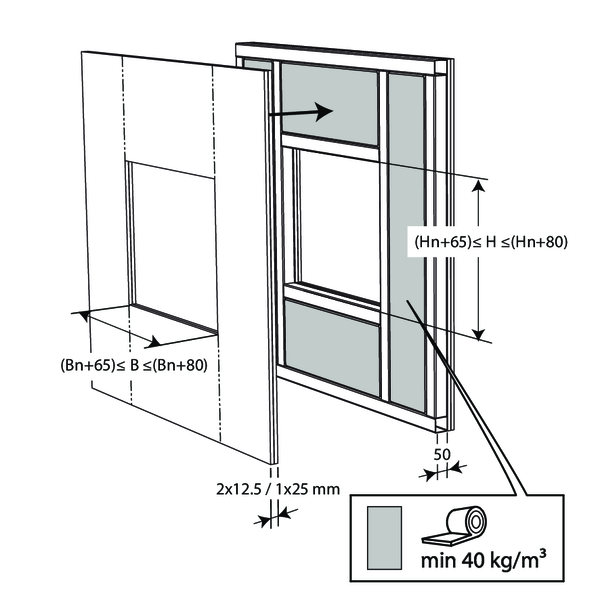
Installation in flexible wall (metal stud gypsum plasterboard wall)
The product was tested and approved in:
- Metal studs gypsum plasterboard Type F (EN 520) ≥ 100 mm | EI 90 (ve i o) S - (500 Pa) | Not applicable | Type of installation: surface-mounted, 0/90/180/270° | 200x100 mm ≤ CU-LT-1s ≤ 800x600 mm
- Metal studs gypsum plasterboard Type A (EN 520) ≥ 100 mm | EI 60 (ve i o) S - (500 Pa) | Not applicable | Type of installation: surface-mounted, 0/90/180/270° | 200x100 mm ≤ CU-LT-1s ≤ 800x600 mm
Installation remote from the wall + GEOFLAM
The product was tested and approved in:
- Aerated concrete ≥ 100 mm | EI 120 (ve i o) S - (500 Pa) | Galvanised duct + GEOFLAM® F 45 mm + mortar | Type of installation: remote from the wall, 0/180° | 200x100 mm ≤ CU-LT-1s ≤ 800x600 mm
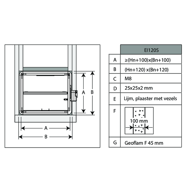
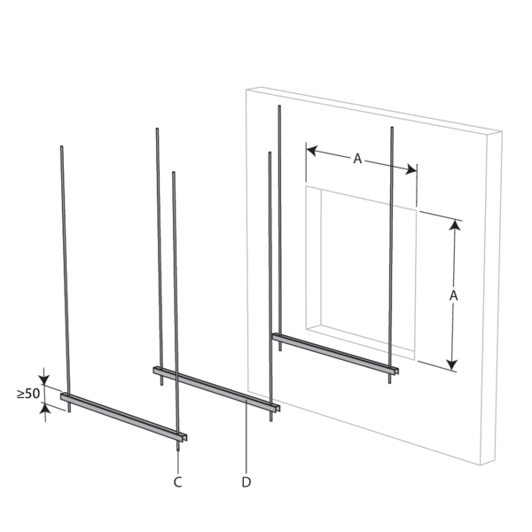
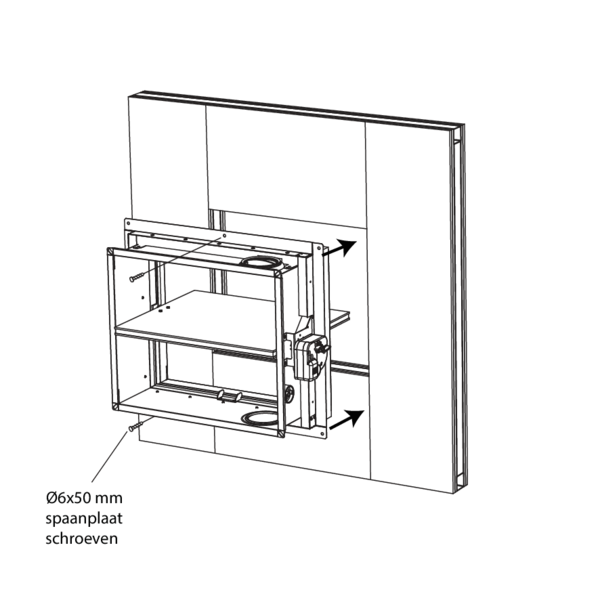
An opening with maximal dimensions “A” is made in the wall.

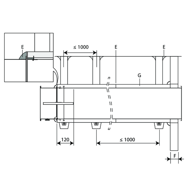
The fire damper is mounted remote from the wall at the end of a metal duct. The duct is supported every 1000 mm.
The suspensions consist of threaded rods “C” and U-shaped steel profiles “D”. A free space of maximum 25 mm is left between the threaded rods and the vertical walls of the casing “B”.
The suspensions consist of threaded rods “C” and U-shaped steel profiles “D”. A free space of maximum 25 mm is left between the threaded rods and the vertical walls of the casing “B”.

The opening around the duct is sealed with standard mortar. The duct is covered with 45 mm thick GEOFLAM F plates or 35 mm thick GEOFLAM Light plates "G”.
The plates adhere to each other with glue and fibrous plaster “E”. The damper casing is also covered on a length of 120 mm.
The plates adhere to each other with glue and fibrous plaster “E”. The damper casing is also covered on a length of 120 mm.
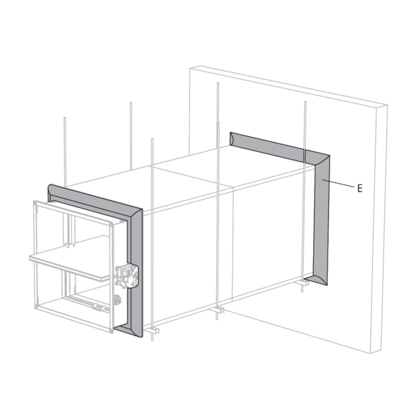
The GEOFLAM F plates stop at a distance of 15 mm from the wall. The free space is filled with fibrous plaster.
The same filling is applied to seal off the connection between the GEOFLAM F plates and the damper casing.
The same filling is applied to seal off the connection between the GEOFLAM F plates and the damper casing.
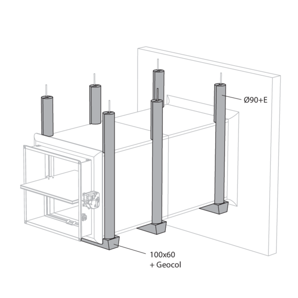
The threaded rods are covered with U-shaped plates of GEOFLAM (Ø 90 mm) and affixed with glue and fibrous plaster.
The profiles are covered with U-shaped shells GEOFLAM 100 x 60 mm, which are affixed to the underside of the shaft with GEOCOL (GEOSTAFF) cement plaster.
The profiles are covered with U-shaped shells GEOFLAM 100 x 60 mm, which are affixed to the underside of the shaft with GEOCOL (GEOSTAFF) cement plaster.
General remarks
- The installation must comply with the installation manual and the classification report.
- Axis orientation: see the declaration of performance.
- Avoid obstruction of adjoining ducts.
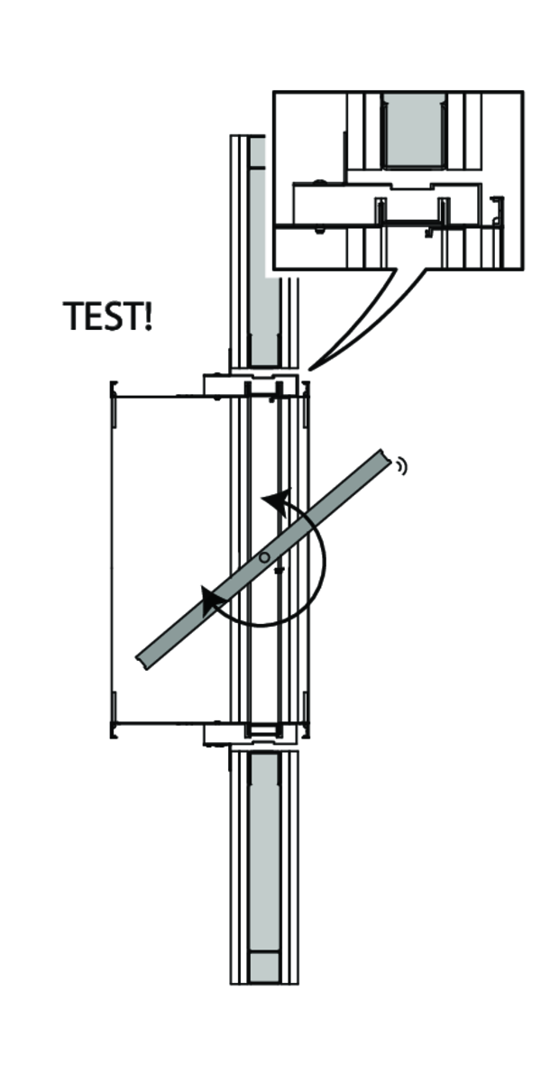
- Product installation: always with closed damper blade.
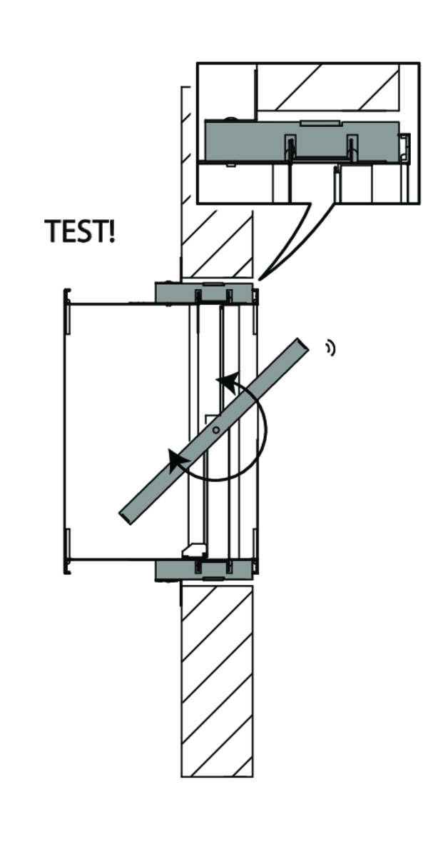
- Verify if the blade can move freely.
- Please observe safety distances with respect to other construction elements. The operating mechanism must also remain accessible: allow for a clearance of 200 mm around the housing.
- The air tightness class will be maintained if the damper is installed according to the installation manual.
- Rf-t fire dampers are always tested in standardised constructions according to EN 1366-2. The achieved results are valid for similar supporting constructions with a fire resistance, thickness and density equal or superior to the supporting construction used during the test.
- If the wall thickness exceeds the minimum thickness specified in our installation instructions, the following conditions apply to the sealing depth: - For flexible walls and sandwich panel system walls, the seal must always be applied over the full depth of the wall. - With rigid walls, rigid floors and plaster block walls, the minimum sealing depth as indicated in our installation instructions (often equal to the minimum wall thickness) is sufficient. Apply the seal at the height of the damper blade (from the wall limit indication).
- When installing a fire damper in a flexible metal stud wall, some installation methods do not require reinforcing profiles around the wall opening from a fire protection point of view (see below). Always follow the general instructions of the manufacturer of these wall systems when building this type of wall.
- The damper must remain accessible for inspection and maintenance.
- Schedule at least 2 visual checks each year.