CU2/B-L500 - Installation
Installation at a minimal distance from another damper or from an adjacent supporting construction
Principle
According to the European test standard, a fire damper must be installed at a minimum distance of 75 mm from an adjacent wall and 200 mm from another damper, unless the solution was tested at a shorter distance.
According to the European test standard, a fire damper must be installed at a minimum distance of 75 mm from an adjacent wall and 200 mm from another damper, unless the solution was tested at a shorter distance.
Installation in rigid wall
The product was tested and approved in:
- Reinforced concrete ≥ 110 mm | EI 120 (ve i o) S - (500 Pa) | Mortar | Type of installation: built-in 0/180° (B22, B21, B12) | CU2/B ≤ 4 x CU2 (200x200 mm ≤ CU2 ≤ 1200x800 mm)
- Reinforced concrete ≥ 110 mm | EI 60 (ve i o) S - (500 Pa) | Mortar | Type of installation: built-in 0/180° (B22, B21, B12) | CU2/B ≤ 4 x CU2 (200x200 mm ≤ CU2 ≤ 1500x800 mm)
- Reinforced concrete ≥ 110 mm | EI 120 (ve i o) S - (300 Pa) | Mortar | Type of installation: built-in 0/180° (B22, B21, B12) | CU2/B ≤ 4 x CU2 (200x200 mm ≤ CU2 ≤ 1500x800 mm)
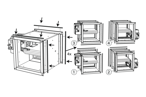
Cut the delivered EPDM foam to the correct sizes.
Stick it on the edges of the individual dampers' flanges as illustrated (i.e. the sides that connect with other individual dampers).
Stick it on the edges of the individual dampers' flanges as illustrated (i.e. the sides that connect with other individual dampers).
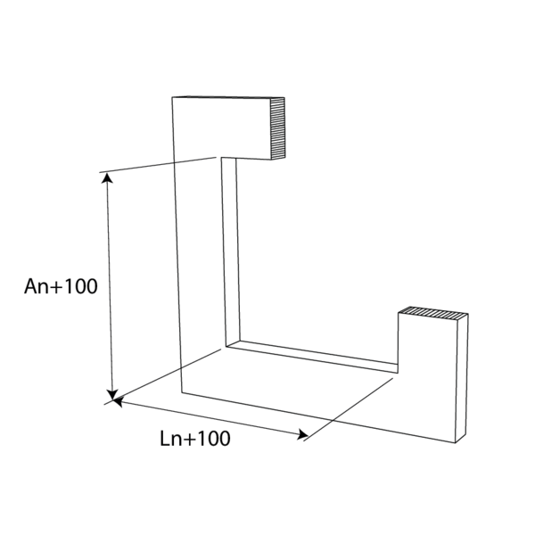
Provide in the wall an installation opening of minimum (Hn+100) mm x (Wn+100) mm
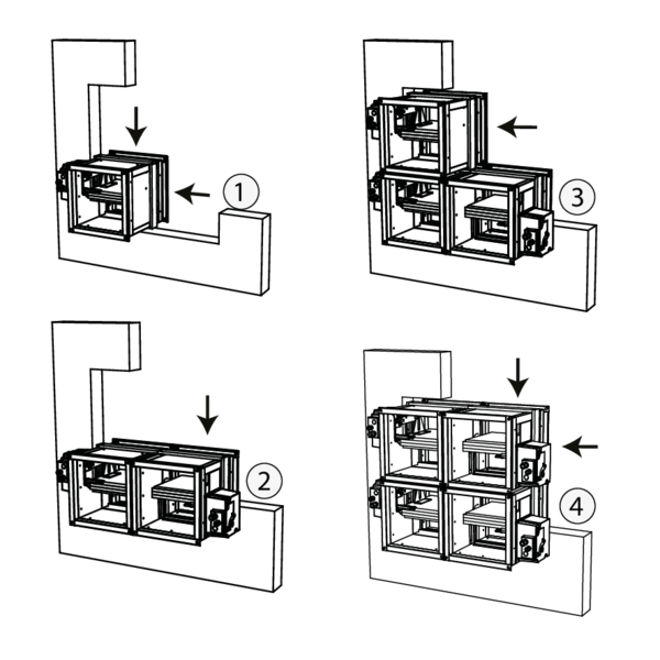
Mount the first individual damper in the opening.
Mount the following dampers in the opening. Every individual damper needs to exceed the wall by 240 mm on the side of the mechanism.
As the mechanism needs to be accessible at all times, you need to provide a free working space of min. 200 mm. If the mechanism is not accessible you need to provide an inspection shutter (e.g. false ceiling).
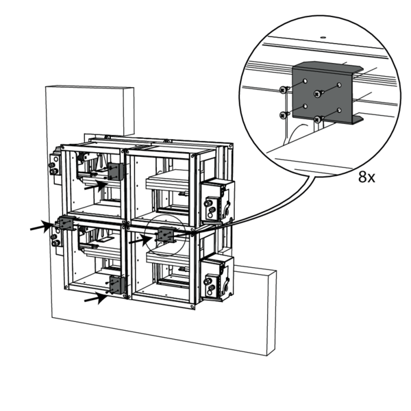
Fix the connection pieces with 4 self drilling screws on the front and back side of the individual dampers.
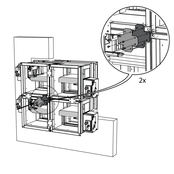
For a battery assembly B22: fix the center plate with 8 self drilling screws at the front and back sides of the battery assembly.
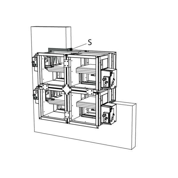
The joint S between the damper and the wall needs to be filled along the whole width of the wall with a standard concrete mortar.
Support the body and block the damper blade in its closed position to prevent deformation of the body during the drying process of the sealing.
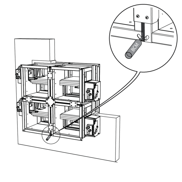
Check for openings in between the individual dampers.
Seal the openings with adhesive BCM.
Run a test on the mechanisms of the fire dampers.
Check for openings in between the individual dampers.
Seal the openings with adhesive BCM.
Run a test on the mechanisms of the fire dampers.
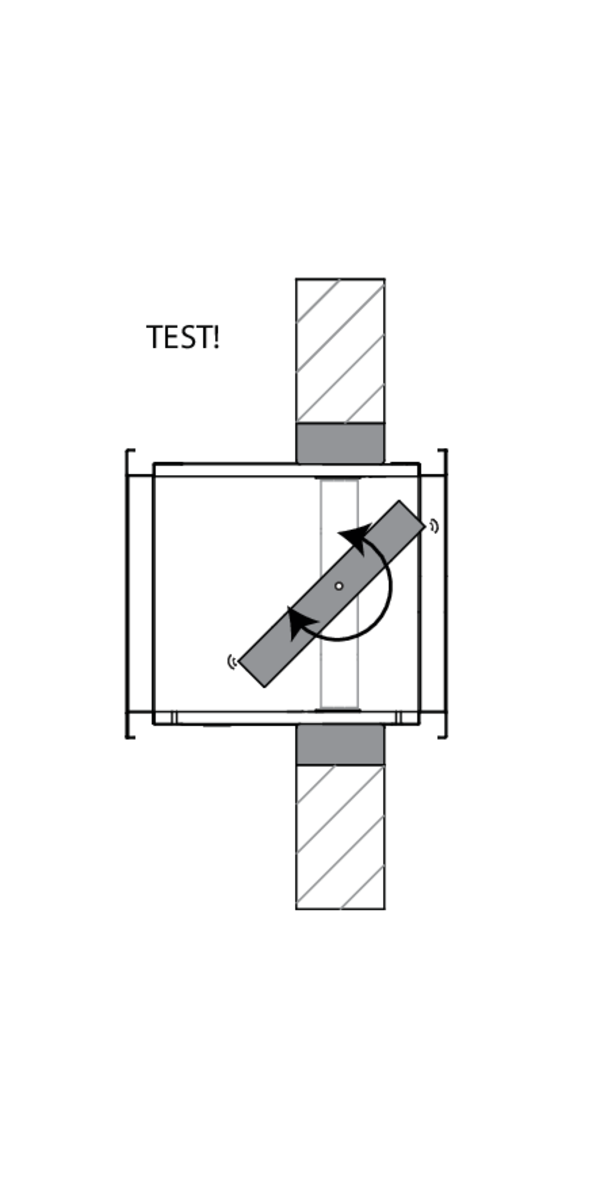
Check the functioning of the damper blades.
General remarks
- The installation must comply with the installation manual and the classification report.
- Axis orientation: see the declaration of performance.
- Avoid obstruction of adjoining ducts.
- Product installation: always with closed damper blade.
- Verify if the blade can move freely.
- Please observe safety distances with respect to other construction elements. The operating mechanism must also remain accessible: allow for a clearance of 200 mm around the housing.
- The air tightness class will be maintained if the damper is installed according to the installation manual.
- Rf-t fire dampers are always tested in standardised constructions according to EN 1366-2. The achieved results are valid for similar supporting constructions with a fire resistance, thickness and density equal or superior to the supporting construction used during the test.
- If the wall thickness exceeds the minimum thickness specified in our installation instructions, the following conditions apply to the sealing depth: - For flexible walls and sandwich panel system walls, the seal must always be applied over the full depth of the wall. - With rigid walls, rigid floors and plaster block walls, the minimum sealing depth as indicated in our installation instructions (often equal to the minimum wall thickness) is sufficient. Apply the seal at the height of the damper blade (from the wall limit indication).
- When installing a fire damper in a flexible metal stud wall, some installation methods do not require reinforcing profiles around the wall opening from a fire protection point of view (see below). Always follow the general instructions of the manufacturer of these wall systems when building this type of wall.
- The damper must remain accessible for inspection and maintenance.
- Schedule at least 2 visual checks each year.