CU2L ATEX - Installation
Installation at a minimal distance from another damper or from an adjacent supporting construction
Principle
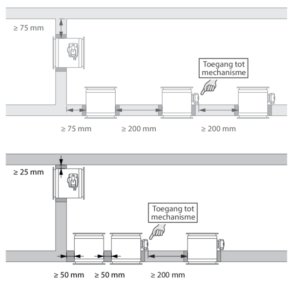
According to the European test standard, a fire damper must be installed at a minimum distance of 75 mm from an adjacent wall and 200 mm from another damper, unless the solution was tested at a shorter distance. This range of Rf-t fire dampers has been successfully tested and can be installed in a vertical or horizontal supporting construction, at a distance below the minimum set by the standard.
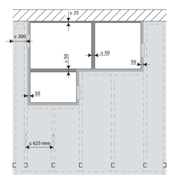
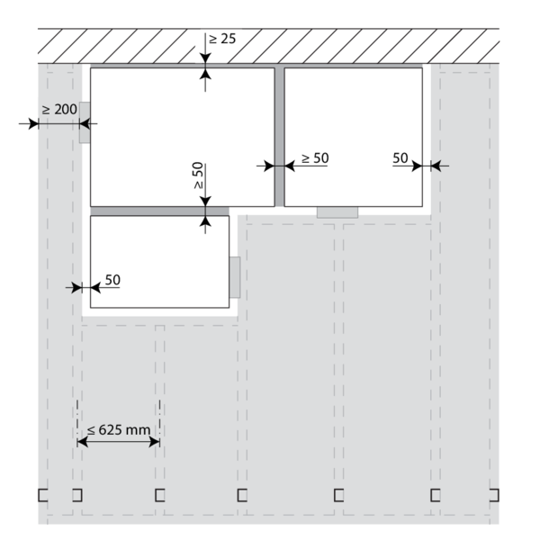
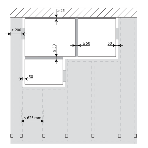
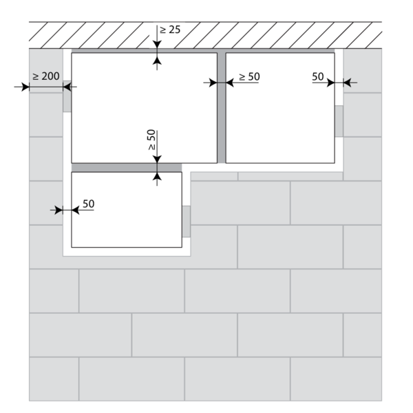
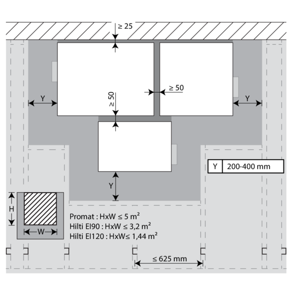
For rectangular dampers, the minimal distance is set to 50 mm between 2 dampers or between a damper and a vertical wall, and to 25 mm between a damper and a floor/ceiling.
According to the European test standard, a fire damper must be installed at a minimum distance of 75 mm from an adjacent wall and 200 mm from another damper, unless the solution was tested at a shorter distance. This range of Rf-t fire dampers has been successfully tested and can be installed in a vertical or horizontal supporting construction, at a distance below the minimum set by the standard.
For rectangular dampers, the minimal distance is set to 50 mm between 2 dampers or between a damper and a vertical wall, and to 25 mm between a damper and a floor/ceiling.
Certified solution
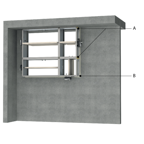
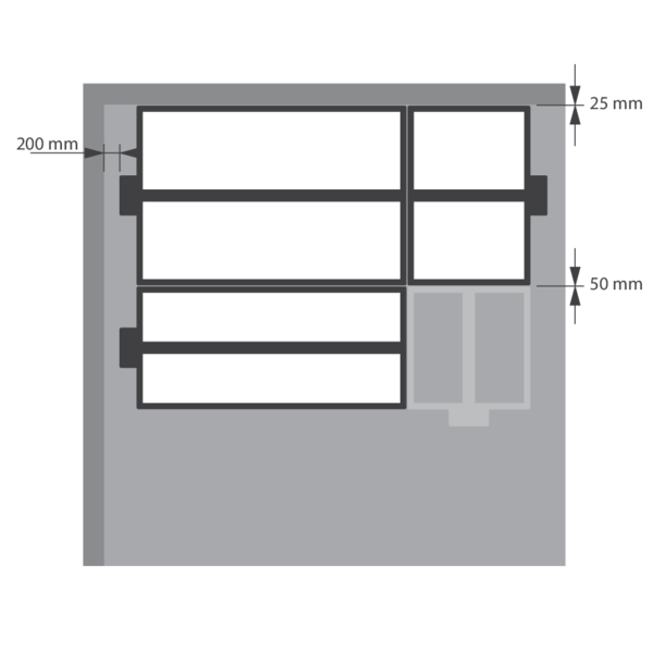
For the Rf-t fire dampers, the solution consists of the following elements: A: Universal sealing for minimal distance; B: Sealing compliant with existing classifications (Declaration of Performance).
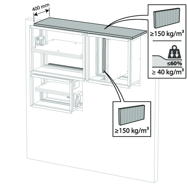
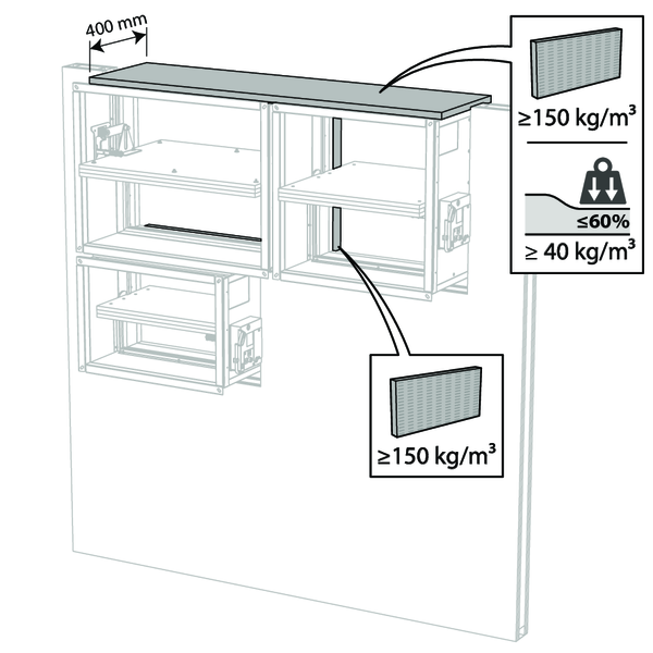
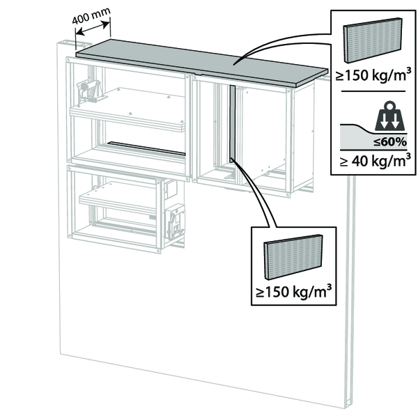
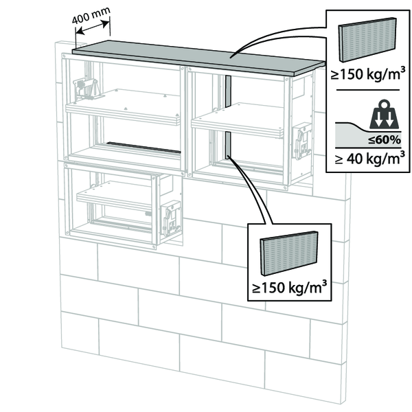
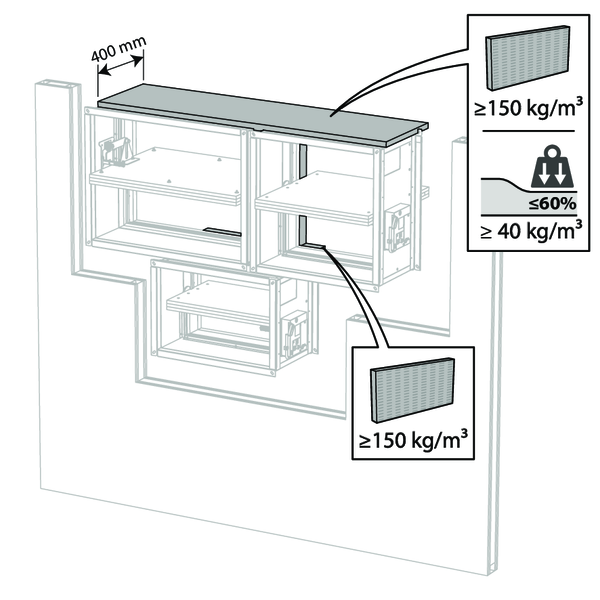
A. Sealing of the opening at the side with minimal distances between damper and wall/ceiling or another fire damper: rigid stone wool panels (150 kg/m³) are applied to a depth of min. 400 mm, of which 150 mm on the mechanism side of the wall. On the non-mechanism side of the wall, the stone wool panels must be at least flush with the wall.
This sealing is applied over the whole width/height of the damper(s).
When the damper is installed at a distance of 25 mm from a floor/ceiling, the rigid high-density stone wool panels (A) may be replaced with standard 40 kg/m³ stone wool, compressed by at least 40%.
B. Sealing of the rest of the opening according to the existing classifications for the fire damper (Declaration of Performance).
Detailed information for each wall/sealing combination can be found in the respective installation methods.
For the Rf-t fire dampers, the solution consists of the following elements: A: Universal sealing for minimal distance; B: Sealing compliant with existing classifications (Declaration of Performance).
A. Sealing of the opening at the side with minimal distances between damper and wall/ceiling or another fire damper: rigid stone wool panels (150 kg/m³) are applied to a depth of min. 400 mm, of which 150 mm on the mechanism side of the wall. On the non-mechanism side of the wall, the stone wool panels must be at least flush with the wall.
This sealing is applied over the whole width/height of the damper(s).
When the damper is installed at a distance of 25 mm from a floor/ceiling, the rigid high-density stone wool panels (A) may be replaced with standard 40 kg/m³ stone wool, compressed by at least 40%.
B. Sealing of the rest of the opening according to the existing classifications for the fire damper (Declaration of Performance).
Detailed information for each wall/sealing combination can be found in the respective installation methods.
Restrictions
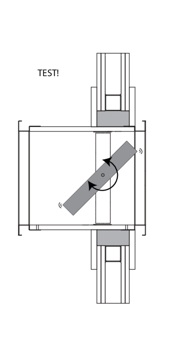
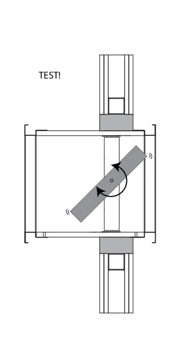
The installer may choose the direction of the blade axis freely: horizontal or vertical axis.
A maximum of 2 rectangular dampers can be installed at a minimum distance from one another, both vertically and horizontally (maximum cluster of 4 dampers).
Note: when sealing the opening with panels of fire resistant stone wool, the maximum number of dampers also depends on the maximum “blank seal” allowed for the selected sealing material. Please refer to the manufacturer's instructions for this information.
Installation in rigid wall and floor
The product was tested and approved in:
- Aerated concrete ≥ 100 mm | EI 120 (ve i o) S - (500 Pa) | Gypsum | Type of installation: built-in 0/180°. Minimal distances authorised. | 200x200 mm ≤ CU2 ≤ 1500x1000 mm
- Aerated concrete ≥ 100 mm | EI 90 (ve i o) S - (300 Pa) | Mortar | Type of installation: built-in 0/180°. Minimal distances authorised. | 200x200 mm ≤ CU2 ≤ 1500x1000 mm
- Aerated concrete ≥ 150 mm | EI 120 (ho i o) S - (500 Pa) | Mortar | Type of installation: built-in 0/90/180/270°. Minimal distances authorised. | 200x200 mm ≤ CU2 ≤ 1500x1000 mm
- Aerated concrete ≥ 100 mm | EI 120 (ve i o) S - (500 Pa) | Mortar | Type of installation: built-in 0/90/180/270°. Minimal distances authorised. | 200x200 mm ≤ CU2 ≤ 1200x800 mm
- Aerated concrete ≥ 100 mm | EI 90 (ve i o) S - (500 Pa) | Gypsum | Type of installation: built-in 0/90/180/270°. Minimal distances authorised. | 200x200 mm ≤ CU2 ≤ 1200x800 mm
- Aerated concrete ≥ 100 mm | EI 60 (ve i o) S - (500 Pa) | Mortar / Gypsum | Type of installation: built-in 0/90/180/270°. Minimal distances authorised. | 1200x800 mm < CU2 ≤ 1500x1000 mm
- Aerated concrete ≥ 100 mm | E 120 (ve i o) S - (500 Pa) | Mortar / Gypsum | Type of installation: built-in 0/90/180/270°. Minimal distances authorised. | 1200x800 mm < CU2 ≤ 1500x1000 mm
- Aerated concrete ≥ 100 mm | EI 90 (ve i o) S - (300 Pa) | Mortar | Type of installation: built-in 0/90/180/270°. Minimal distances authorised. | 1200x800 mm < CU2 ≤ 1500x800 mm
- Aerated concrete ≥ 125 mm | EI 120 (ho i o) S - (300 Pa) | Mortar | Type of installation: built-in 0/90/180/270°. Minimal distances authorised. | 200x200 mm ≤ CU2 ≤ 1500x800 mm
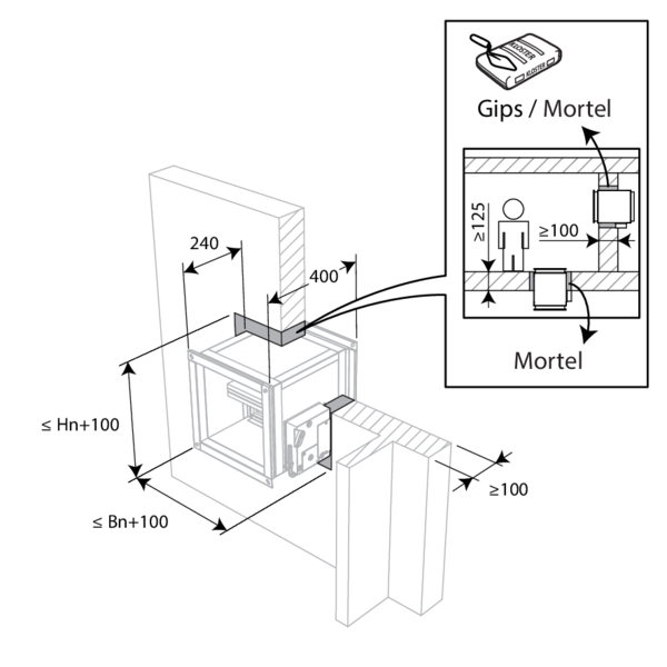

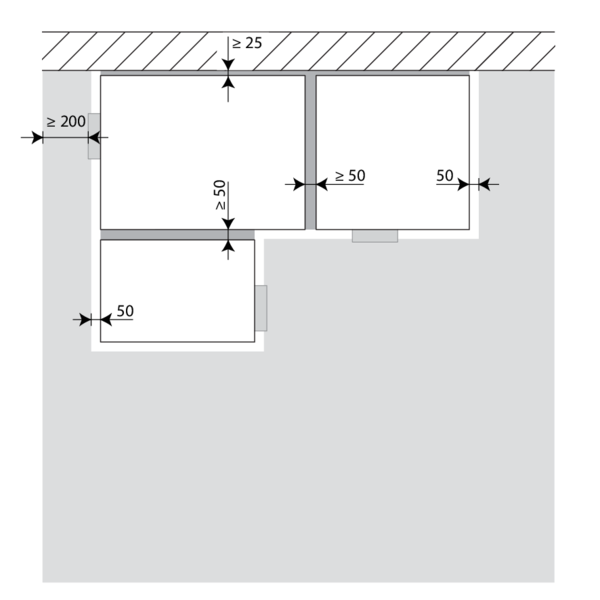
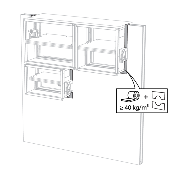
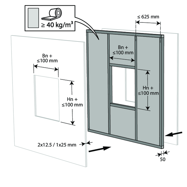
The dampers can be installed at a minimum distance from an adjacent floor/ceiling (≥ 25 mm), from an adjacent wall or from another damper (≥ 50 mm).
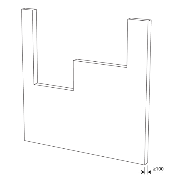
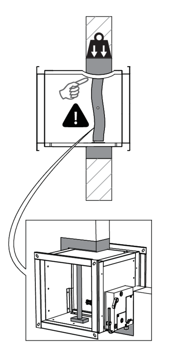
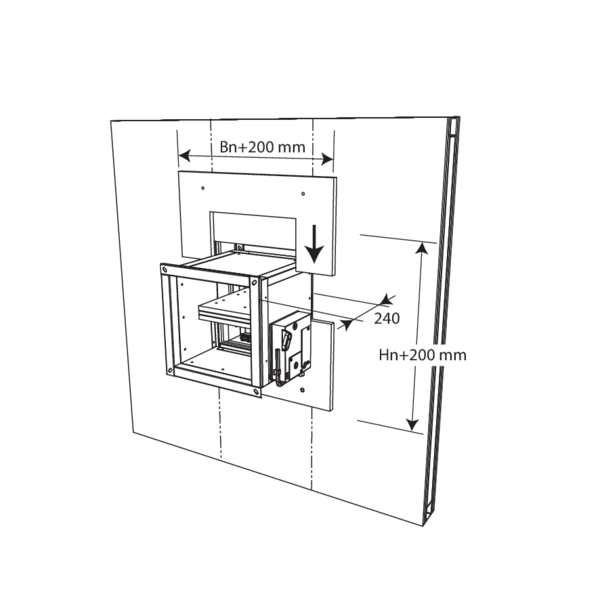
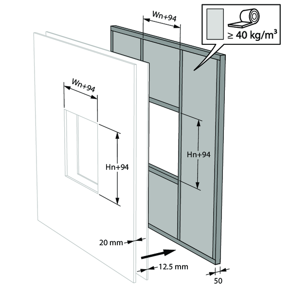
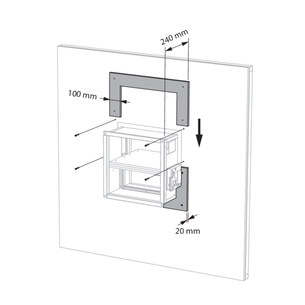
Make the necessary openings (Wn + 100 mm) x (Hn + 100 mm) in the wall.
Mount the dampers in the opening.
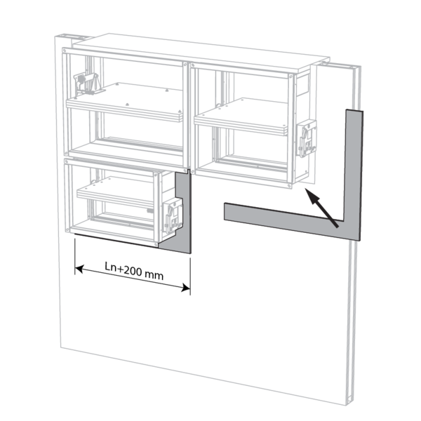
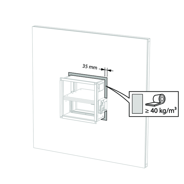
Apply rigid stone wool panels (≥ 150 kg/m³) to a depth of 400 mm (150 mm on the mechanism side of the wall) to seal the opening at the side with minimal distances.
This sealing is applied over the whole width/height of the damper(s).
When the damper is installed at a distance of 25 mm from a floor/ceiling, the rigid high-density stone wool panels may be replaced with standard ≥ 40 kg/m³ stone wool (e.g. Rockfit 431), compressed by at least 40%.
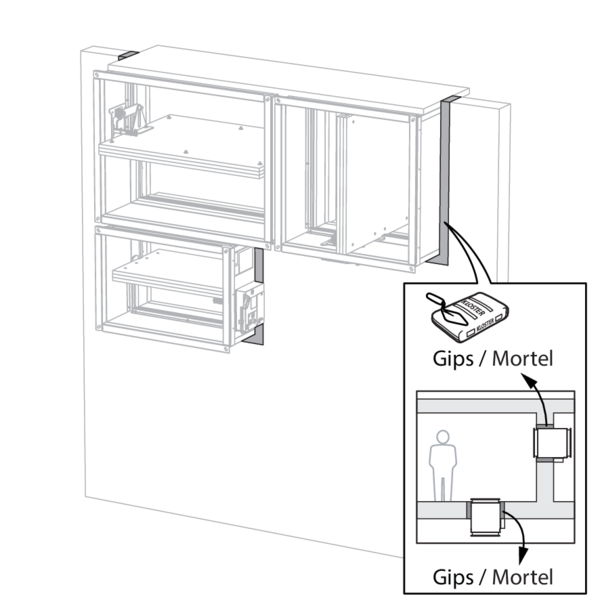
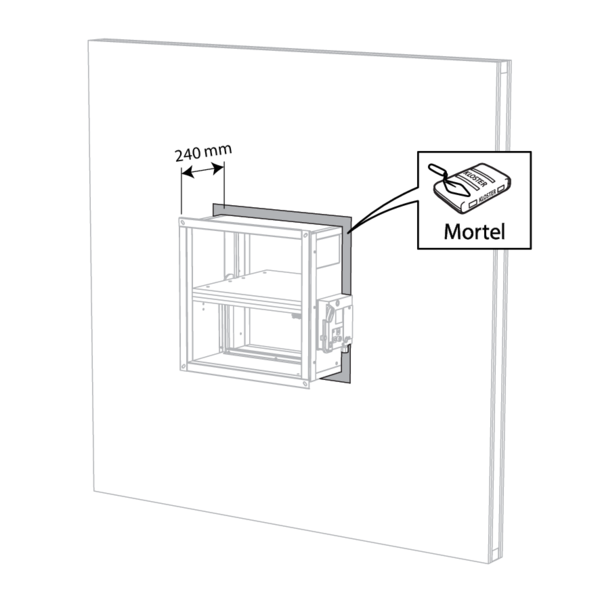
Seal the rest of the opening with standard mortar or gypsum (only for vertical walls).
Installation in flexible wall (metal stud gypsum plasterboard wall)
The product was tested and approved in:
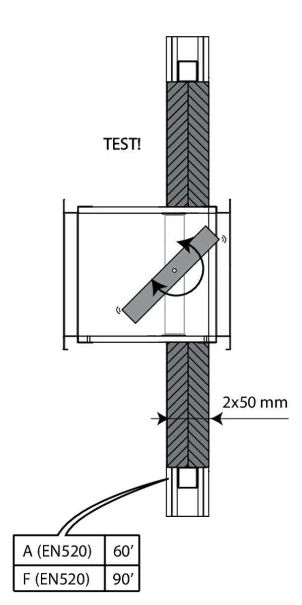
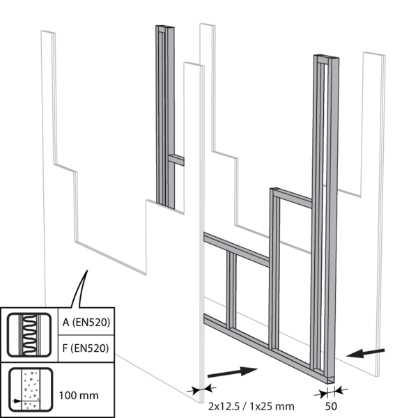
- Metal studs gypsum plasterboard Type A (EN 520) ≥ 100 mm | EI 60 (ve i o) S - (500 Pa) | Stone wool ≥ 40 kg/m³ + cover plates | Type of installation: built-in 0/180°. Minimal distances authorised. | 200x200 mm ≤ CU2 ≤ 1200x800 mm
- Metal studs gypsum plasterboard Type F (EN 520) ≥ 100 mm | EI 90 (ve i o) S - (500 Pa) | Stone wool ≥ 40 kg/m³ + cover plates | Type of installation: built-in 0/180°. Minimal distances authorised. | 200x200 mm ≤ CU2 ≤ 1200x800 mm
- Metal studs gypsum plasterboard Type F (EN 520) ≥ 100 mm | EI 90 (ve i o) S - (300 Pa) | Stone wool ≥ 40 kg/m³ + cover plates | Type of installation: built-in 0/180°. Minimal distances authorised. | 1200x800 mm < CU2 ≤ 1500x800 mm
- Metal studs gypsum plasterboard Type F (EN 520) ≥ 100 mm | E 120 (ve i o) S - (300 Pa) | Stone wool ≥ 40 kg/m³ + cover plates | Type of installation: built-in 0/180°. Minimal distances authorised. | 1200x800 mm < CU2 ≤ 1500x800 mm
The dampers can be installed at a minimum distance from an adjacent floor/ceiling (≥ 25 mm), from an adjacent wall or from another damper (≥ 50 mm).
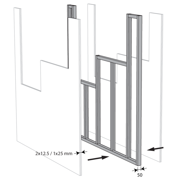
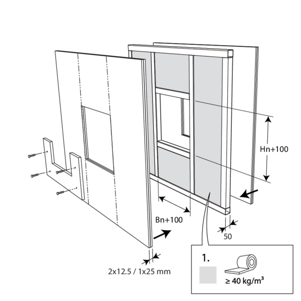
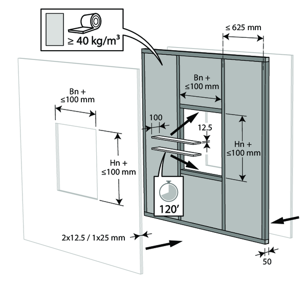
Build the drywall and foresee horizontal and vertical studs around the opening.
Mount the dampers in the opening.
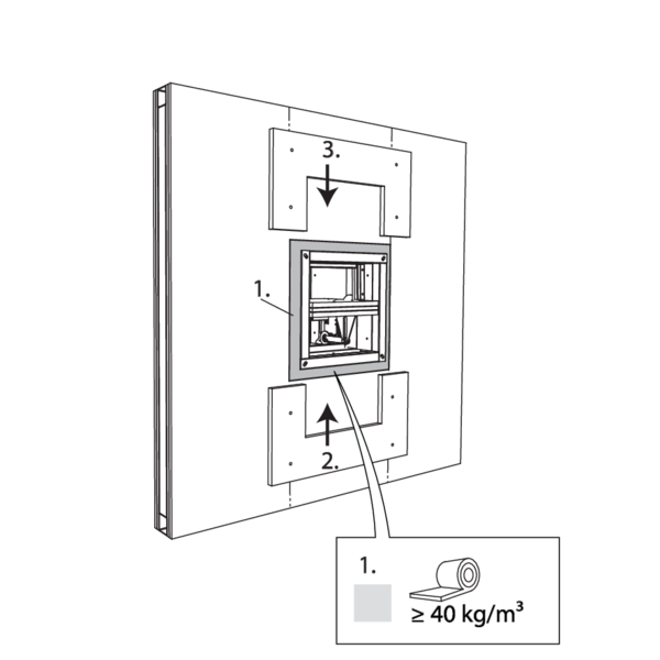
Apply rigid stone wool panels (≥ 150 kg/m³) to a depth of 400 mm (150 mm on the mechanism side of the wall) to seal the opening at the side with minimal distances.
This sealing is applied over the whole width/height of the damper(s).
When the damper is installed at a distance of 25 mm from a floor/ceiling, the rigid high-density stone wool panels may be replaced with standard ≥ 40 kg/m³ stone wool (e.g. Rockfit 431), compressed by at least 40%.
Seal the rest of the opening with standard stone wool 40 kg/m³ across the entire wall thickness.
Apply cover plates (gypsum plasterboards) to finish the surface at both sides.
Seal off the space between the plasterboards with jointfiller.
Seal off the space between the plasterboards with jointfiller.
Installation in flexible wall (metal stud gypsum plasterboard wall), sealing with gypsum
The product was tested and approved in:
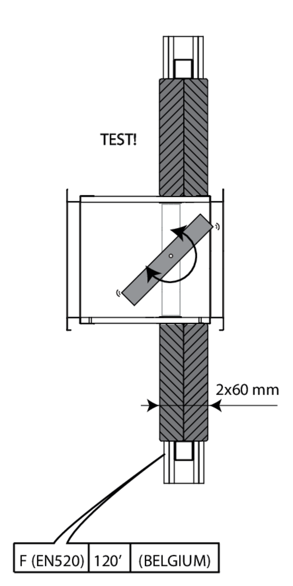
- Metal studs gypsum plasterboard Type F (EN 520) ≥ 100 mm | EI 120 (ve i o) S - (500 Pa) | Gypsum | Type of installation: built-in 0/180°. Minimal distances authorised. | 200x200 mm ≤ CU2 ≤ 1500x1000 mm
- Metal studs gypsum plasterboard Type A (EN 520) ≥ 100 mm | EI 60 (ve i o) S - (500 Pa) | Gypsum | Type of installation: built-in 0/180°. Minimal distances authorised. | 200x200 mm ≤ CU2 ≤ 1200x800 mm
The dampers can be installed at a minimum distance from an adjacent floor/ceiling (≥ 25 mm), from an adjacent wall or from another damper (≥ 50 mm).

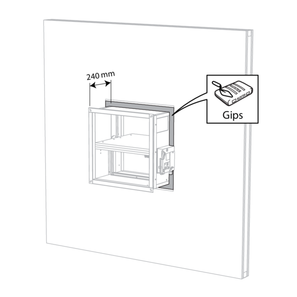
Build the drywall and foresee horizontal and vertical studs around the opening.
Mount the dampers in the opening.
Apply rigid stone wool panels (≥ 150 kg/m³) to a depth of 400 mm (150 mm on the mechanism side of the wall) to seal the opening at the side with minimal distances.
This sealing is applied over the whole width/height of the damper(s).
When the damper is installed at a distance of 25 mm from a floor/ceiling, the rigid high-density stone wool panels may be replaced with standard ≥ 40 kg/m³ stone wool (e.g. Rockfit 431), compressed by at least 40%.
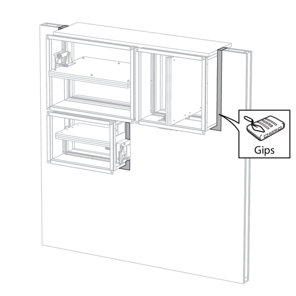
Seal the rest of the opening (50 mm) with standard gypsum across the entire wall thickness.
Installation in flexible wall (metal stud gypsum plasterboard wall), sealing with mortar
The product was tested and approved in:
- Metal studs gypsum plasterboard Type F (EN 520) ≥ 100 mm | EI 90 (ve i o) S - (300 Pa) | Mortar | Type of installation: built-in 0/180°. Minimal distances authorised. | 200x200 mm ≤ CU2 ≤ 1500x1000 mm
The dampers can be installed at a minimum distance from an adjacent floor/ceiling (≥ 25 mm), from an adjacent wall or from another damper (≥ 50 mm).

Build the drywall and foresee horizontal and vertical studs around the opening.

Mount the dampers in the opening.
Apply rigid stone wool panels (≥ 150 kg/m³) to a depth of 400 mm (150 mm on the mechanism side of the wall) to seal the opening at the side with minimal distances.
This sealing is applied over the whole width/height of the damper(s).
When the damper is installed at a distance of 25 mm from a floor/ceiling, the rigid high-density stone wool panels may be replaced with standard ≥ 40 kg/m³ stone wool (e.g. Rockfit 431), compressed by at least 40%.
Apply rigid stone wool panels (≥ 150 kg/m³) to a depth of 400 mm (150 mm on the mechanism side of the wall) to seal the opening at the side with minimal distances.
This sealing is applied over the whole width/height of the damper(s).
When the damper is installed at a distance of 25 mm from a floor/ceiling, the rigid high-density stone wool panels may be replaced with standard ≥ 40 kg/m³ stone wool (e.g. Rockfit 431), compressed by at least 40%.
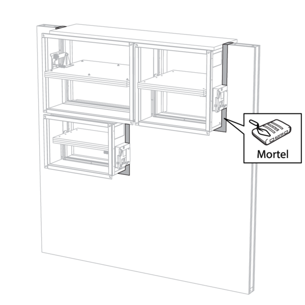
Seal the rest of the opening (50 mm) with standard mortar across the entire wall thickness.
Installation in gypsum block wall
The product was tested and approved in:
- Gypsum blocks ≥ 100 mm | EI 120 (ve i o) S - (500 Pa) | Block glue | Type of installation: built-in 0/180°. Minimal distances authorised. | 200x200 mm ≤ CU2 ≤ 1500x1000 mm
- Gypsum blocks ≥ 70 mm | EI 120 (ve i o) S - (500 Pa) | Block glue | Type of installation: built-in 0/180°. Minimal distances authorised. | 200x200 mm ≤ CU2 ≤ 1200x800 mm
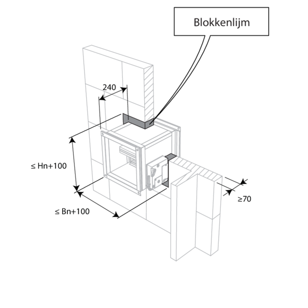
The dampers can be installed at a minimum distance from an adjacent floor/ceiling (≥ 25 mm), from an adjacent wall or from another damper (≥ 50 mm).
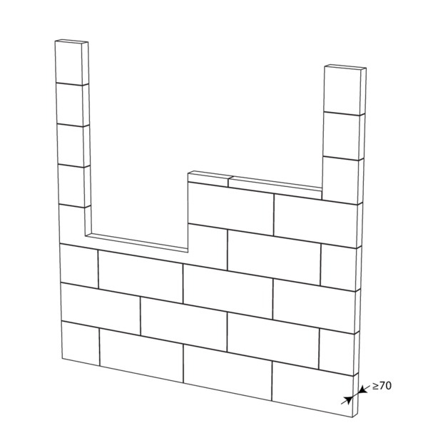
Make the necessary openings (Wn + 100 mm) x (Hn + 100 mm) in the wall.
Mount the dampers in the opening.
Apply rigid stone wool panels (≥ 150 kg/m³) to a depth of 400 mm (150 mm on the mechanism side of the wall) to seal the opening at the side with minimal distances.
This sealing is applied over the whole width/height of the damper(s).
When the damper is installed at a distance of 25 mm from a floor/ceiling, the rigid high-density stone wool panels may be replaced with standard ≥ 40 kg/m³ stone wool (e.g. Rockfit 431), compressed by at least 40%.
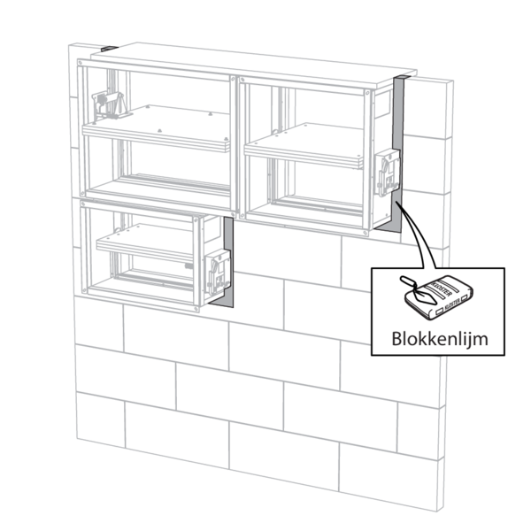
Seal the rest of the opening (50 mm) with block glue across the entire wall thickness.
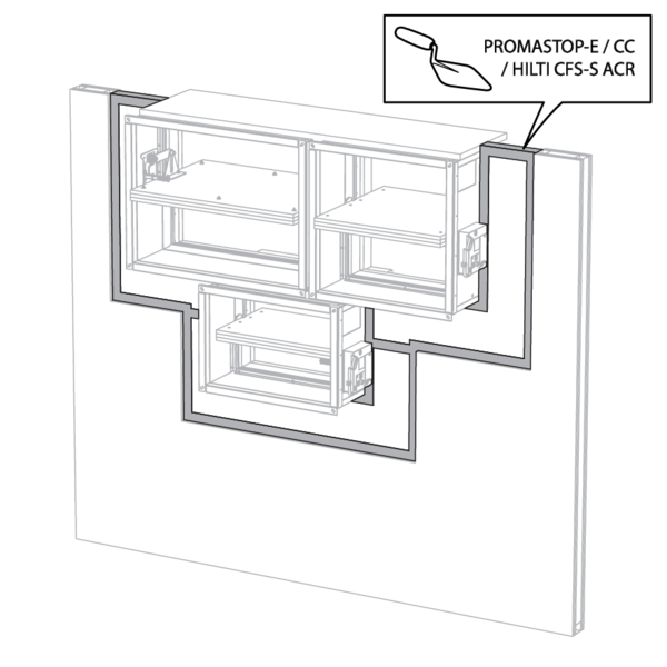
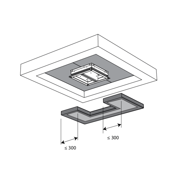
Installation in flexible and rigid wall, sealing with rigid rock wool boards with coating
The product was tested and approved in:
- Aerated concrete ≥ 100 mm | EI 90 (ve i o) S - (300 Pa) | Stone wool + coating ≥ 140 kg/m³ | Type of installation: built-in 0/90/180/270°. Minimal distances authorised. | 200x200 mm ≤ CU2 ≤ 1200x800 mm
- Metal studs gypsum plasterboard Type A (EN 520) ≥ 100 mm | EI 60 (ve i o) S - (300 Pa) | Stone wool + coating ≥ 140 kg/m³ | Type of installation: built-in 0/90/180/270°. Minimal distances authorised. | 200x200 mm ≤ CU2 ≤ 1200x800 mm
- Metal studs gypsum plasterboard Type F (EN 520) ≥ 100 mm | EI 90 (ve i o) S - (300 Pa) | Stone wool + coating ≥ 140 kg/m³ | Type of installation: built-in 0/90/180/270°. Minimal distances authorised. | 200x200 mm ≤ CU2 ≤ 1200x800 mm
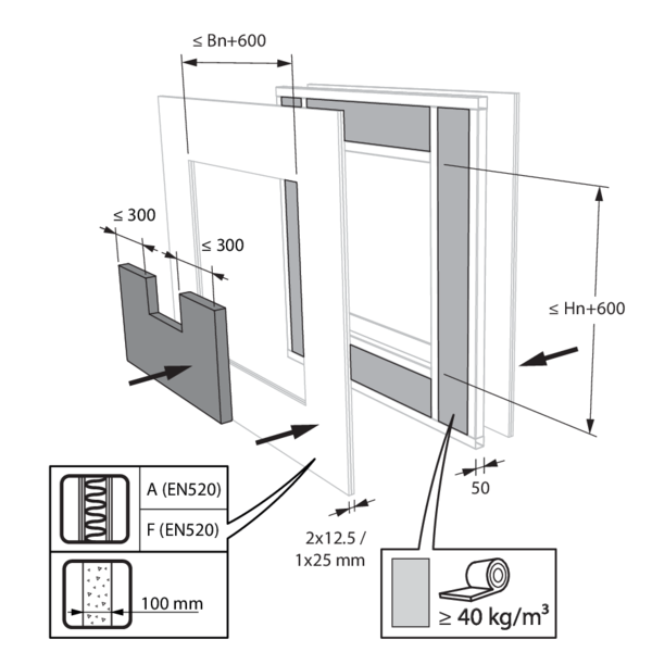
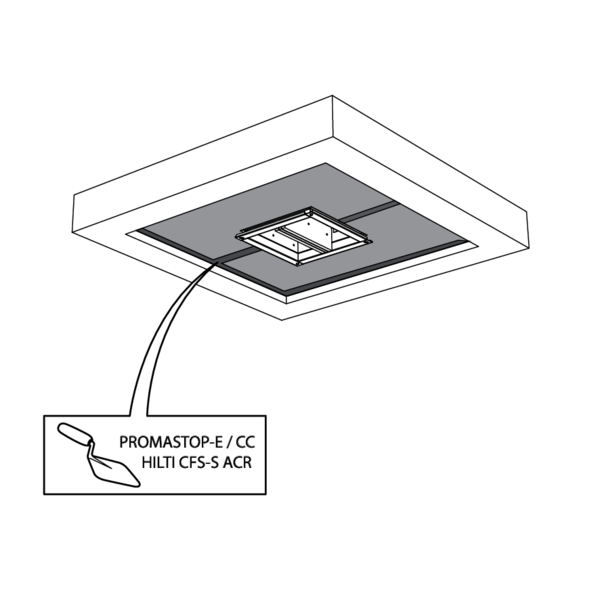
The opening around the damper is sealed with 2 layers of 50 mm-thick mineral wool panels with fire resistant coating on one side (type PROMASTOP-CB 50 / PROMASTOP-CB/CC 50 / HILTI CFS-CT B / Mulcol Multimastic FB1 / PYRO-SAFE® MFP).

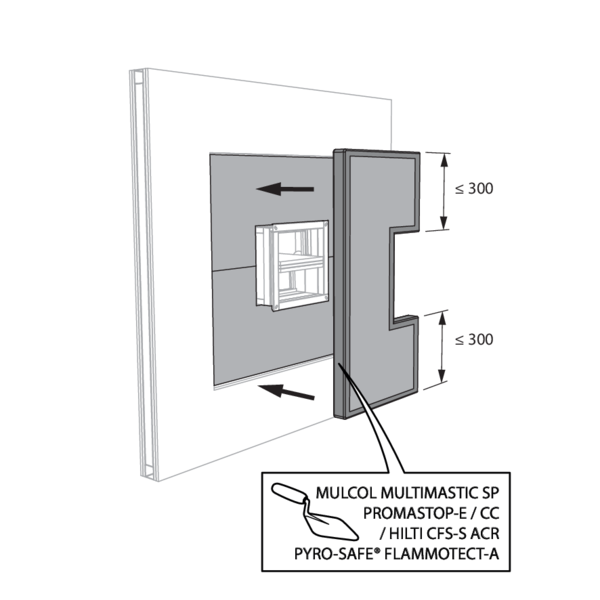
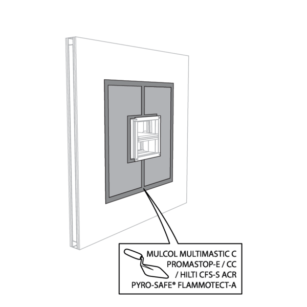
The joints on these 2 layers must be installed staggered and covered all around the edge with coating (type PROMASTOP-E / PROMASTOP-CC / HILTI CFS-S-ACR / Mulcol Multimastic SP / PYRO-SAFE® FLAMMOTECT-A).
The damper does not need to be centered in the opening (with max dimensions fire damper + 600 mm). The maximal distance between the damper and the edge of the opening is 400 mm.
The dampers can be installed at a minimum distance from an adjacent floor/ceiling (≥ 25 mm), from an adjacent wall or from another damper (≥ 50 mm).
Make the necessary opening in the wall.
Mount the dampers in the opening.
Apply rigid stone wool panels (≥ 150 kg/m³) to a depth of 400 mm (150 mm on the mechanism side of the wall) to seal the opening at the side with minimal distances.
This sealing is applied over the whole width/height of the damper(s).
When the damper is installed at a distance of 25 mm from a floor/ceiling, the rigid high-density stone wool panels may be replaced with standard ≥ 40 kg/m³ stone wool (e.g. Rockfit 431), compressed by at least 40%.
Apply rigid stone wool panels (≥ 150 kg/m³) to a depth of 400 mm (150 mm on the mechanism side of the wall) to seal the opening at the side with minimal distances.
This sealing is applied over the whole width/height of the damper(s).
When the damper is installed at a distance of 25 mm from a floor/ceiling, the rigid high-density stone wool panels may be replaced with standard ≥ 40 kg/m³ stone wool (e.g. Rockfit 431), compressed by at least 40%.
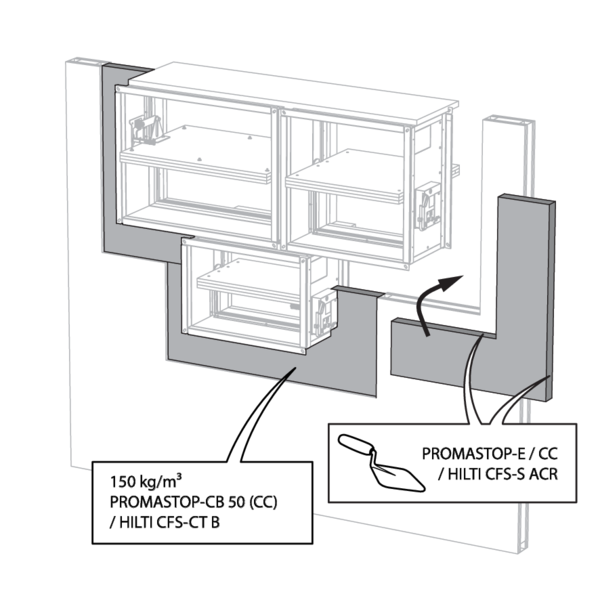
Seal the rest of the opening with 2 layers of 50 mm-thick coated rigid mineral wool panels (see above).
Installation in rigid floor, sealing with rigid rock wool boards with coating
The product was tested and approved in:
- Aerated concrete ≥ 150 mm | EI 90 (ho i o) S - (300 Pa) | Stone wool + coating ≥ 140 kg/m³ | Type of installation: built-in 0/90/180/270°. Minimal distances authorised. | 200x200 mm ≤ CU2 ≤ 1200x800 mm
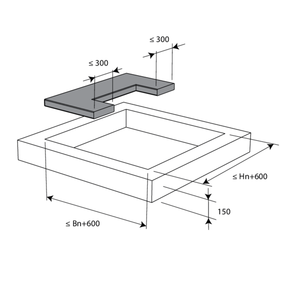
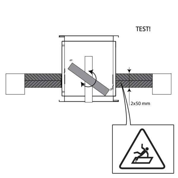
The opening around the damper is sealed with 2 layers of 50 mm-thick mineral wool panels with fire resistant coating on one side (type PROMASTOP-CB 50 / PROMASTOP-CB/CC 50 / HILTI CFS-CT B).
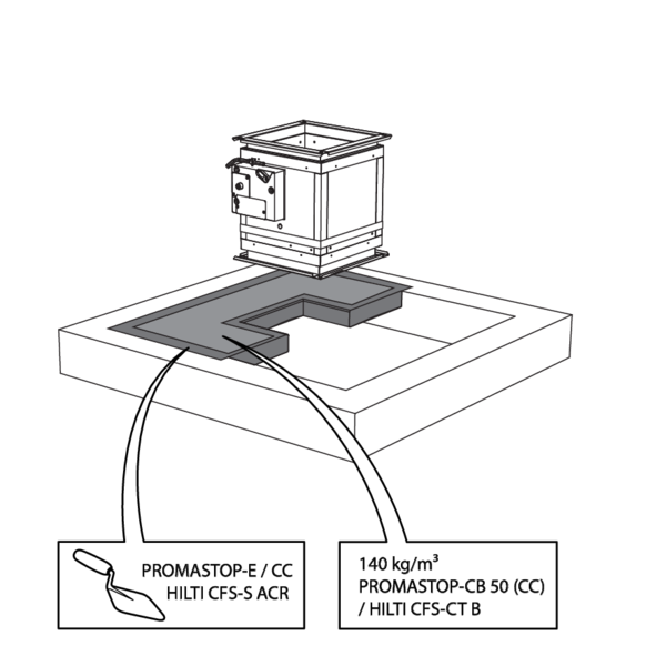
The joints on these 2 layers must be installed staggered and covered all around the edge with coating (type PROMASTOP-E / PROMASTOP-CC / HILTI CFS-S-ACR).
The damper does not need to be centered in the opening (with max dimensions fire damper + 600 mm). The maximal distance between the damper and the edge of the opening is 400 mm.
The dampers can be installed at a minimum distance from an adjacent floor/ceiling (≥ 25 mm), from an adjacent wall or from another damper (≥ 50 mm).
For details, please refer to 'Installation in flexible and rigid wall, sealing with rigid rock wool boards with coating'
For details, please refer to 'Installation in flexible and rigid wall, sealing with rigid rock wool boards with coating'
Installation in shaft wall
The product was tested and approved in:
- Metal studs gypsum plasterboard Type F (EN 520) ≥ 82.5 mm | EI 60 (ve i o) S - (300 Pa) | Stone wool ≥ 40 kg/m³ + cover plates | Type of installation: built-in 0/180° | 200x200 mm ≤ CU2 ≤ 1500x800 mm
Battery assembly
The product was tested and approved in:
- Reinforced concrete ≥ 110 mm | EI 120 (ve i o) S - (500 Pa) | Mortar | Type of installation: built-in 0/180° (B22, B21, B12) | CU2/B ≤ 4 x CU2 (200x200 mm ≤ CU2 ≤ 1200x800 mm)
- Reinforced concrete ≥ 110 mm | EI 60 (ve i o) S - (500 Pa) | Mortar | Type of installation: built-in 0/180° (B22, B21, B12) | CU2/B ≤ 4 x CU2 (200x200 mm ≤ CU2 ≤ 1500x800 mm)
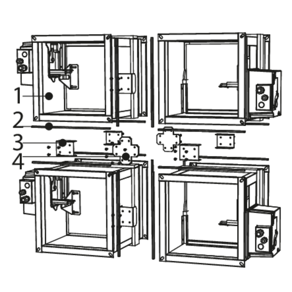
1. Individual damper CU2; 2. EPDM foam; 3. Connection piece; 4. Center plate - B22 (see technical note C31)
General remarks
- The installation must comply with the installation manual and the classification report.
- Axis orientation: see the declaration of performance.
- Avoid obstruction of adjoining ducts.
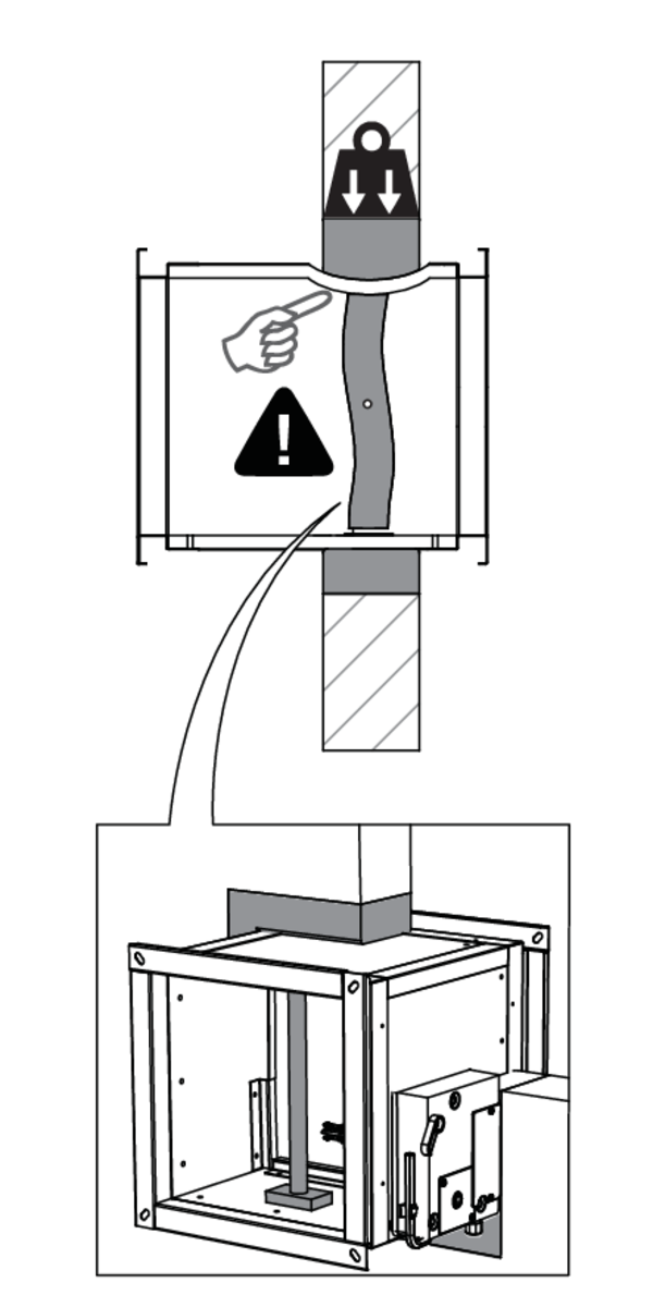
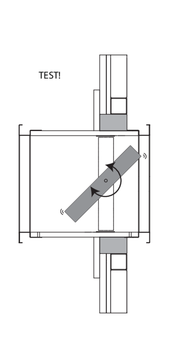
- Product installation: always with closed damper blade.
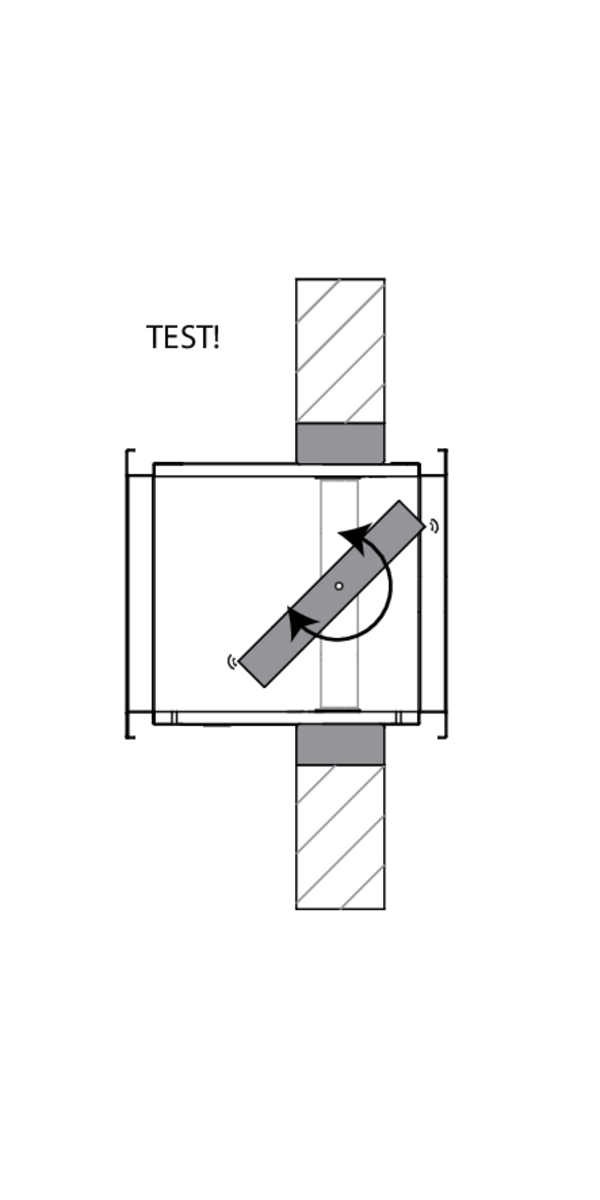
- Verify if the blade can move freely.
- Please observe safety distances with respect to other construction elements. The operating mechanism must also remain accessible: allow for a clearance of 200 mm around the housing.
- The air tightness class will be maintained if the damper is installed according to the installation manual.
- Rf-t fire dampers are always tested in standardised constructions according to EN 1366-2. The achieved results are valid for similar supporting constructions with a fire resistance, thickness and density equal or superior to the supporting construction used during the test.
- If the wall thickness exceeds the minimum thickness specified in our installation instructions, the following conditions apply to the sealing depth: - For flexible walls and sandwich panel system walls, the seal must always be applied over the full depth of the wall. - With rigid walls, rigid floors and plaster block walls, the minimum sealing depth as indicated in our installation instructions (often equal to the minimum wall thickness) is sufficient. Apply the seal at the height of the damper blade (from the wall limit indication).
- When installing a fire damper in a flexible metal stud wall, some installation methods do not require reinforcing profiles around the wall opening from a fire protection point of view (see below). Always follow the general instructions of the manufacturer of these wall systems when building this type of wall.
- The damper must remain accessible for inspection and maintenance.
- Schedule at least 2 visual checks each year.