VUW120 - Installation
Installation in rigid wall
The product was tested and approved in:
- Aerated concrete ≥ 100 mm | EI 120 (vew i o) S 1500 AA multi C10000 | Mortar | Type of installation: built-in 0/180° | 300x300 mm ≤ VUW120 ≤ 1500x1000 mm
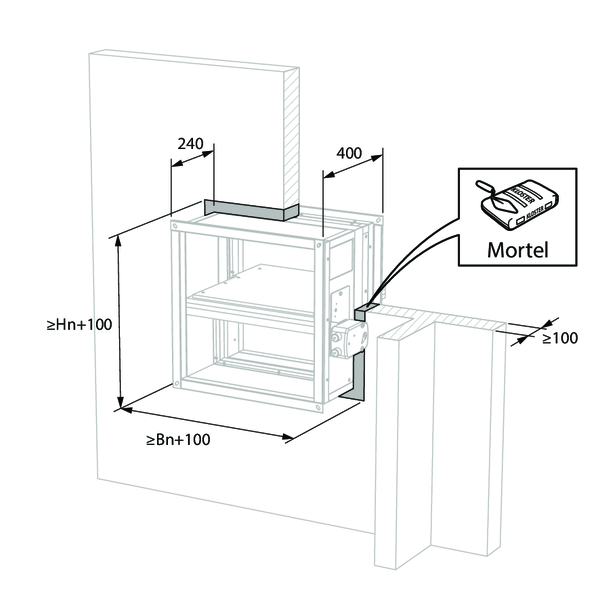
Make the necessary openings (Wn + 100 mm) x (Hn + 100 mm) in the wall.
Mount the damper in the opening.
Seal the rest of the opening with standard mortar.
Mount the damper in the opening.
Seal the rest of the opening with standard mortar.
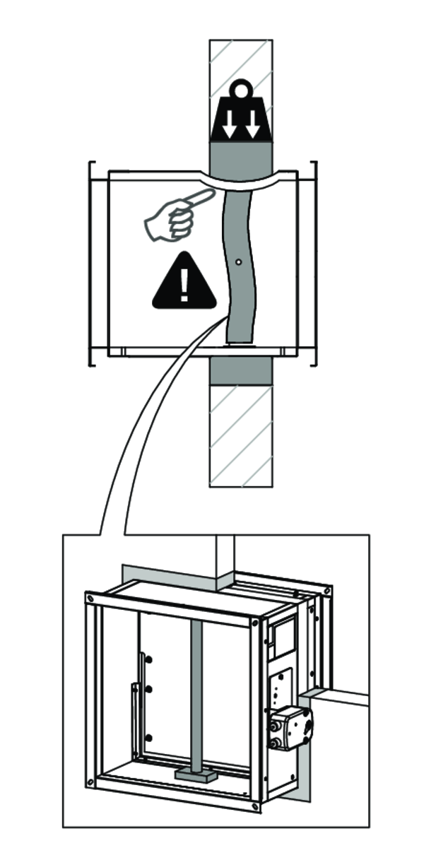
Support the body and block the damper blade in its closed position to prevent deformation of the body during the drying process of the sealing.
Check the movement of the damper blade.
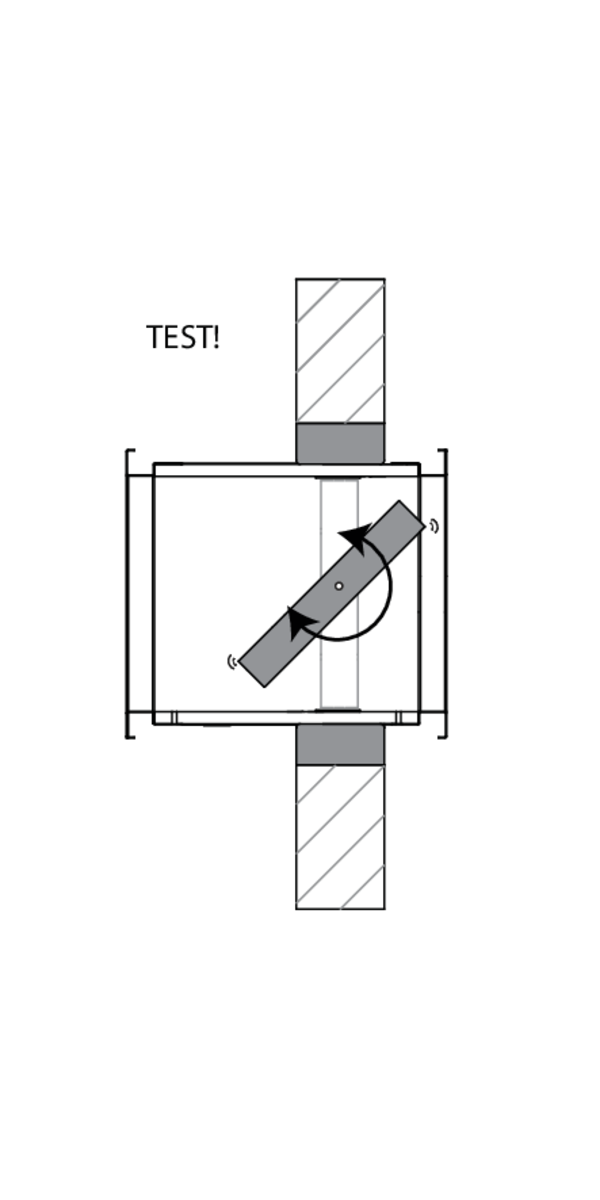
Test the mechanism of the damper.
Test the mechanism of the damper.
Installation in a multi / single compartment application
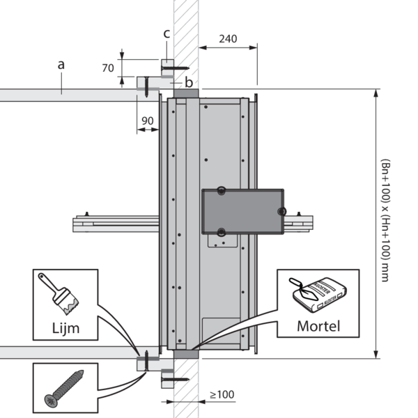
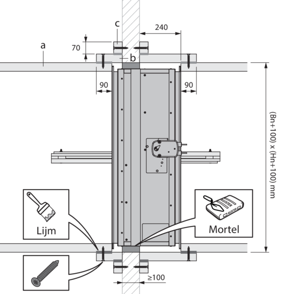
The multi compartment smoke extraction duct (a), made of refractory material of ≥ 50 mm thickness, is positioned against the flange of the damper. A frame (b), made of the same refractory material of ≥ 50 mm, connects the smoke extraction duct with the wall. This frame has an overlay on the duct of at least 90mm. The frame is connected to the duct using screws (ø5x90 mm) every 150 mm and corresponding duct glue. An additional flange (c) of 70 mm height, made of the same refractory material of 50 mm or thicker, is screwed to the wall using screws suitable for that wall.
Material used: Promatect L500 ≥ 50 mm Duct glue: Promat K84 Screws: coarse thread ø5x90
Material used: Promatect L500 ≥ 50 mm Duct glue: Promat K84 Screws: coarse thread ø5x90
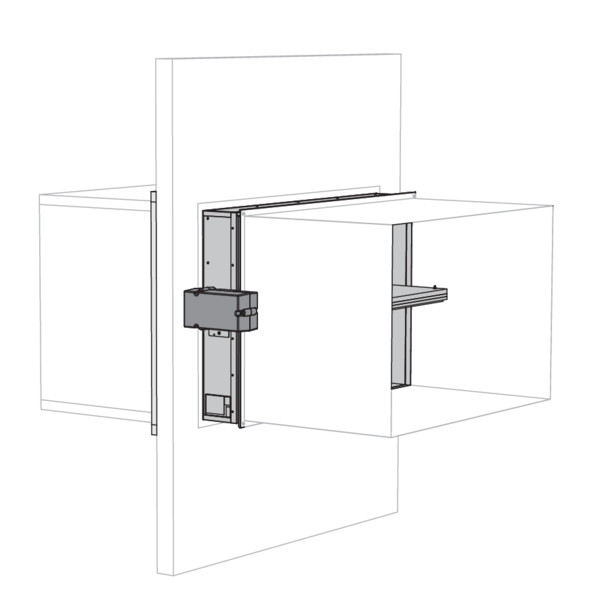
If required, connect single compartment smoke extraction ducts using the PG30 flange on the VUW120. The actuator could be protected by a thermal insulating box. This is not a requirement for the AA classification.
Installation with multi compartment application on both sides
The multi compartment smoke extraction ducts (a), made of refractory material of ≥ 50 mm thickness, is positioned on both sides of the damper. A frame (b), made of the same refractory material of ≥ 50 mm, connects the smoke extraction ducts to the wall. These frames have an overlay on the duct of at least 90mm. The frames are connected to the duct using screws (ø5x90 mm) every 150 mm and corresponding duct glue. Additional flanges (c) of 70mm height, made of the same refractory material of 50mm or thicker, are screwed to the wall using screws suitable for that wall.
Material used: Promatect L500 ≥ 50 mm Duct glue: Promat K84 Screws: coarse thread ø5x90
Material used: Promatect L500 ≥ 50 mm Duct glue: Promat K84 Screws: coarse thread ø5x90
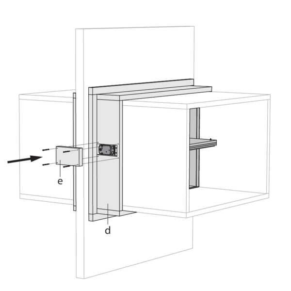
On the mechanism side, make an opening in frame (d) of 230 x 110 mm to access the actuator. Make a cover plate (e) of 280 x 210 mm made of the same refractory material of 50 mm or thicker. This will be used to cover the actuator, using 4 screws of ø5x90 mm. Caulk around the electrical cables with fire resistant sealant (such as BMS f.e.).
General remarks
- The installation must comply with the installation manual and the classification report.
- The installation of the smoke control duct must comply with the classification report delivered by the manufacturer.
- Axis orientation: see the declaration of performance.
- Avoid the obstruction of adjoining smoke control ducts.
- Verify if the blade can move freely.
- Rf-t smoke dampers may be applied to smoke control ducts that have been tested according to EN 1366-8 and EN 1366-9 as appropriate, constructed from similar materials with a fire resistance, thickness and density equal or superior to these of the tested materials.
- Caution: when fitting, the product should be handled with care and remain protected from any sealing products.
- Caution: before putting the installation into operation, clean off all the dust and dirt.
- Caution: bear in mind the blade’s clearance inside the smoke control duct.