VU120 - Installation
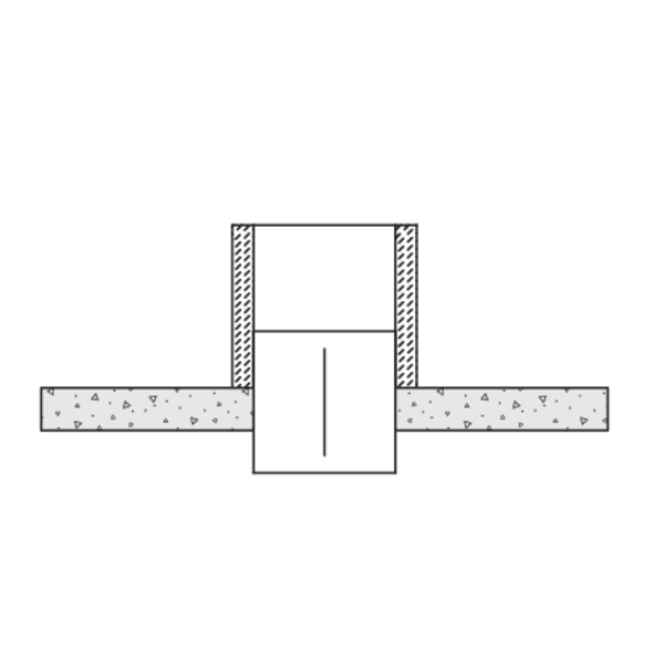
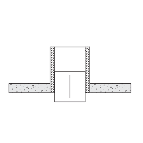
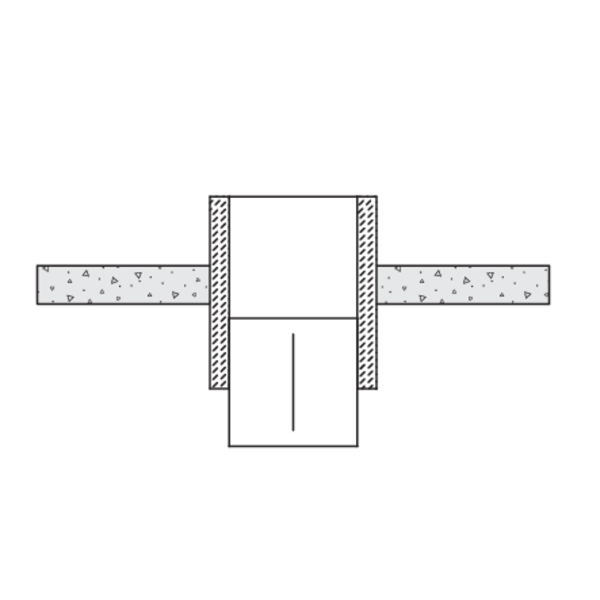
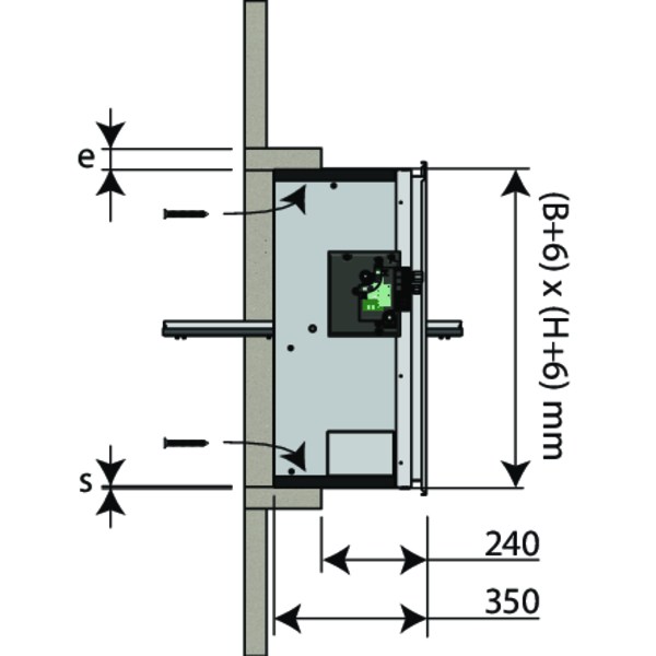
Installation in duct - cross section view
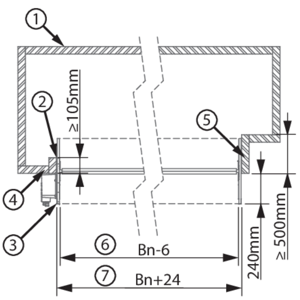
1. Duct
2. Sealing
3. PG30 flange
4. Mounting without duct extension
5. Mounting with duct extension
6. Inside dimensions casing (Wn-6) x (Hn-6)
7. Outside dimensions casing (Wn+24) x (Hn+24)
2. Sealing
3. PG30 flange
4. Mounting without duct extension
5. Mounting with duct extension
6. Inside dimensions casing (Wn-6) x (Hn-6)
7. Outside dimensions casing (Wn+24) x (Hn+24)
Installation into horizontal or vertical duct PROMATECT L500
The product was tested and approved in:
- Promatect L500 ≥ 30 mm | EI 60 (ved hod i o) S 1500 AA multi | Gap between duct and damper (≤ 6 mm) sealed with refractory kit (on a depth ≥ 105 mm) | Type of installation: in duct/shaft-mounted 0/90°/180°/270° | 200x200 mm ≤ VU120+MANF/BEN + grill ≤ 1200x800 mm; 1000x1000. 200x200 mm ≤ VU120+NF/SF + grill ≤ 1200x650 mm; 950x750 mm
- Promatect L500 ≥ 40 mm | EI 90 (ved hod i o) S 1500 AA multi | Gap between duct and damper (≤ 6 mm) sealed with refractory kit (on a depth ≥ 105 mm) | Type of installation: in duct/shaft-mounted 0/90°/180°/270° | 200x200 mm ≤ VU120+MANF/BEN + grill ≤ 1200x800 mm; 1000x1000. 200x200 mm ≤ VU120+NF/SF + grill ≤ 1200x650 mm; 950x750 mm
- Promatect L500 ≥ 50 mm | EI 120 (ved hod i o) S 1500 AA multi | Gap between duct and damper (≤ 6 mm) sealed with refractory kit (on a depth ≥ 105 mm) | Type of installation: in duct/shaft-mounted 0/90°/180°/270° | 200x200 mm ≤ VU120+MANF/BEN + grill ≤ 1200x800 mm; 1000x1000. 200x200 mm ≤ VU120+NF/SF + grill ≤ 1200x650 mm; 950x750 mm
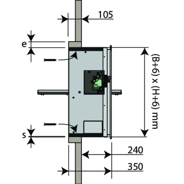
Make an opening with dimensions (W+A) x (H+A) mm. A = 2 x thickness sleeve (e) + 6 mm.
Fit a sleeve of the same type of material and thickness as the duct (thickness e) of minimum 105 mm deep in the opening.
Fix the sleeve to the duct wall.
First coat the opening with Promacol S.
Position the damper in the opening and fix the damper using 12 screws Ø5x60 (horizontal duct) or using 10 screws Ø5x60 (vertical duct).
Caution: make sure that the bolts don't exceed the sleeve's thickness!
The seal between the casing and the duct (S) must be completely filled with refractory coating (type Promacol S). Support the tunnel or tighten the blade in its closed position to prevent deformation of the casing during drying of the sealing material.
Fix the grill to the flange using glue type Polyflex.
Check the movement of the damper blade.
Test the mechanism of the damper.
Installation into horizontal or vertical duct GEOFLAM (LIGHT)
The product was tested and approved in:
- Geoflam ≥ 30 mm | EI 60 (ved hod i o) S 1500 AA multi | Gap between duct and damper (≤ 80 mm) sealed with refractory kit (on a depth ≥ 105 mm) | Type of installation: in duct/shaft-mounted 0/90°/180°/270° | 200x200 mm ≤ VU120+MANF/BEN + grill ≤ 1200x800 mm; 1000x1000. 200x200 mm ≤ VU120+NF/SF + grill ≤ 1200x650 mm; 950x750 mm
- Geoflam ≥ 35 mm | EI 90 (ved hod i o) S 1500 AA multi | Gap between duct and damper (≤ 80 mm) sealed with refractory kit (on a depth ≥ 105 mm) | Type of installation: in duct/shaft-mounted 0/90°/180°/270° | 200x200 mm ≤ VU120+MANF/BEN + grill ≤ 1200x800 mm; 1000x1000. 200x200 mm ≤ VU120+NF/SF + grill ≤ 1200x650 mm; 950x750 mm
- Geoflam ≥ 45 mm | EI 120 (ved hod i o) S 1500 AA multi | Gap between duct and damper (≤ 80 mm) sealed with refractory kit (on a depth ≥ 105 mm) | Type of installation: in duct/shaft-mounted 0/90°/180°/270° | 200x200 mm ≤ VU120+MANF/BEN + grill ≤ 1200x800 mm; 1000x1000. 200x200 mm ≤ VU120+NF/SF + grill ≤ 1200x650 mm; 950x750 mm
- Geoflam Light ≥ 35 mm | EI 120 (ved hod i o) S 1500 AA multi | Gap between duct and damper (≤ 80 mm) sealed with refractory kit (on a depth ≥ 105 mm) | Type of installation: in duct/shaft-mounted 0/90°/180°/270° | 200x200 mm ≤ VU120+MANF/BEN + grill ≤ 1200x800 mm; 1000x1000. 200x200 mm ≤ VU120+NF/SF + grill ≤ 1200x650 mm; 950x750 mm
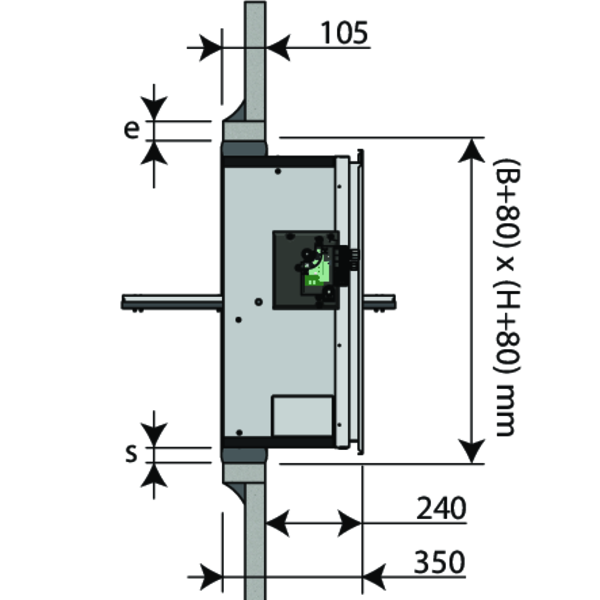
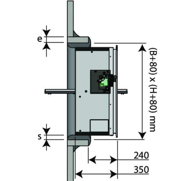
Make an opening with dimensions (W+80) x (H+80) mm.
Fit a sleeve of the same type of material and thickness as the duct (thickness e) of minimum 105 mm deep in the opening.
Seal the joints between uprights and cross pieces and between the lining and the wall with vegetable fibre caulking and plaster.
The sealing between the casing and the duct (S) must be completely filled with fibre reinforced plaster. Support the tunnel or tighten the blade in its closed position to prevent deformation of the casing during drying of the sealing material.
Fix the grill to the flange using glue type Polyflex.
Check the movement of the damper blade.
Test the mechanism of the damper.
Installation into horizontal or vertical duct GEOTEC
The product was tested and approved in:
- Geotec ≥ 30 mm | EI 60 (ved hod i o) S 1500 AA multi | Gap between duct and damper (≤ 80 mm) sealed with refractory kit (on a depth ≥ 105 mm) | Type of installation: in duct/shaft-mounted 0/90°/180°/270° | 200x200 mm ≤ VU120+MANF/BEN + grill ≤ 1200x800 mm; 1000x1000. 200x200 mm ≤ VU120+NF/SF + grill ≤ 1200x650 mm; 950x750 mm
- Geotec ≥ 45 mm | EI 120 (ved hod i o) S 1500 AA multi | Gap between duct and damper (≤ 80 mm) sealed with refractory kit (on a depth ≥ 105 mm) | Type of installation: in duct/shaft-mounted 0/90°/180°/270° | 200x200 mm ≤ VU120+MANF/BEN + grill ≤ 1200x800 mm; 1000x1000. 200x200 mm ≤ VU120+NF/SF + grill ≤ 1200x650 mm; 950x750 mm
Make an opening with dimension (W+80) x (H+80) mm (if sealing with a mixture of plaster and sisal fibre) or an opening with dimension (W+6) x (H+6) mm (if sealing with glue and screws).
Fit a sleeve of the same type of material and thickness as the duct (thickness e) of minimum 105 mm deep in the opening.
Seal the joints between uprights and cross pieces and between the lining and the wall with vegetable fibre caulking and plaster or attach the sleeve to the duct wall with adhesive and screws Ø 5 x (2 x e) mm in 100 mm increments.
Mount the damper in the opening.
The sealing between the casing and the duct (S) must be completely filled with fibre reinforced plaster or with GEOCOL glue and screws. Support the tunnel or tighten the blade in its closed position to prevent deformation of the casing during drying of the sealing material.
Fix the grill to the flange using glue type Polyflex.
Check the movement of the damper blade.
Test the mechanism of the damper.
Installation into horizontal or vertical duct TECNIVER
The product was tested and approved in:
- Tecniver ≥ 35 mm | EI 60 (ved hod i o) S 1500 AA multi | Gap between duct and damper (≤ 6 mm) sealed with refractory kit (on a depth ≥ 105 mm) | Type of installation: in duct/shaft-mounted 0/90°/180°/270° | 200x200 mm ≤ VU120+MANF/BEN + grill ≤ 1200x800 mm; 1000x1000. 200x200 mm ≤ VU120+NF/SF + grill ≤ 1200x650 mm; 950x750 mm
- Tecniver ≥ 45 mm | EI 90 (ved hod i o) S 1500 AA multi | Gap between duct and damper (≤ 6 mm) sealed with refractory kit (on a depth ≥ 105 mm) | Type of installation: in duct/shaft-mounted 0/90°/180°/270° | 200x200 mm ≤ VU120+MANF/BEN + grill ≤ 1200x800 mm; 1000x1000. 200x200 mm ≤ VU120+NF/SF + grill ≤ 1200x650 mm; 950x750 mm
- Tecniver ≥ 50 mm | EI 120 (ved hod i o) S 1500 AA multi | Gap between duct and damper (≤ 6 mm) sealed with refractory kit (on a depth ≥ 105 mm) | Type of installation: in duct/shaft-mounted 0/90°/180°/270° | 200x200 mm ≤ VU120+MANF/BEN + grill ≤ 1200x800 mm; 1000x1000. 200x200 mm ≤ VU120+NF/SF + grill ≤ 1200x650 mm; 950x750 mm
Make an opening with dimensions (W+A) x (H+A) mm. A = 2 x thickness sleeve (e) + 6 mm.
Fit a sleeve of the same type of material and thickness as the duct (thickness e) of minimum 105 mm deep in the opening.
Fix the sleeve to the duct wall.
Put glue CF GLUE on the edges of the opening and the uprights and cross pieces.
Position the damper in the opening and fix the damper using 12 screws Ø5x60 (horizontal duct) or using 10 screws Ø5x60 (vertical duct).
Caution: make sure that the bolts don't exceed the sleeve's thickness!
The seal between the casing and the duct (S) must be completely filled with glue (type type CF glue). Support the tunnel or tighten the blade in its closed position to prevent deformation of the casing during drying of the sealing material.
Fix the grill to the flange using glue type Polyflex.
Check the movement of the damper blade.
Test the mechanism of the damper.
Installation into horizontal or vertical duct GLASROC F V500
The product was tested and approved in:
- Glasroc F V500 ≥ 35 mm | EI 60 (ved hod i o) S 1500 AA multi | Gap between duct and damper (≤ 6 mm) sealed with refractory kit (on a depth ≥ 105 mm) | Type of installation: in duct/shaft-mounted 0/90°/180°/270° | 200x200 mm ≤ VU120+MANF/BEN + grill ≤ 1200x800 mm; 1000x1000. 200x200 mm ≤ VU120+NF/SF + grill ≤ 1200x650 mm; 950x750 mm
- Glasroc F V500 ≥ 50 mm | EI 120 (ved hod i o) S 1500 AA multi | Gap between duct and damper (≤ 6 mm) sealed with refractory kit (on a depth ≥ 105 mm) | Type of installation: in duct/shaft-mounted 0/90°/180°/270° | 200x200 mm ≤ VU120+MANF/BEN + grill ≤ 1200x800 mm; 1000x1000. 200x200 mm ≤ VU120+NF/SF + grill ≤ 1200x650 mm; 950x750 mm
Make an opening with dimensions (W+A) x (H+A) mm. A = 2 x thickness sleeve (e) + 6 mm.
Fit a sleeve of the same type of material and thickness as the duct (thickness e) of minimum 105 mm deep in the opening.
Fix the sleeve to the duct wall.
Put glue GLASROC F V500 on the edges of the opening and the uprights and cross pieces.
Position the damper in the opening and fix the damper using 12 screws Ø5x60 (horizontal duct) or using 10 screws Ø5x60 (vertical duct).
Caution: make sure that the bolts don't exceed the sleeve's thickness!
The sealing between the casing and the duct (S) must be completely filled with glue (type Glasroc F V500). Support the casing or tighten the blade in its closed position to prevent deformation of the casing during drying of the sealing material.
Fix the grill to the flange using glue type Polyflex.
Check the movement of the damper blade.
Test the mechanism of the damper.
Installation into horizontal or vertical duct EXTHAMAT
The product was tested and approved in:
- Exthamat ≥ 25 mm | EI 60 (ved hod i o) S 1500 AA multi | Gap between duct and damper (≤ 80 mm) sealed with refractory kit (on a depth ≥ 105 mm) | Type of installation: in duct/shaft-mounted 0/90°/180°/270° | 200x200 mm ≤ VU120+MANF/BEN + grill ≤ 1200x800 mm; 1000x1000. 200x200 mm ≤ VU120+NF/SF + grill ≤ 1200x650 mm; 950x750 mm
- Exthamat ≥ 30 mm | EI 90 (ved hod i o) S 1500 AA multi | Gap between duct and damper (≤ 80 mm) sealed with refractory kit (on a depth ≥ 105 mm) | Type of installation: in duct/shaft-mounted 0/90°/180°/270° | 200x200 mm ≤ VU120+MANF/BEN + grill ≤ 1200x800 mm; 1000x1000. 200x200 mm ≤ VU120+NF/SF + grill ≤ 1200x650 mm; 950x750 mm
- Exthamat ≥ 35 mm | EI 120 (ved hod i o) S 1500 AA multi | Gap between duct and damper (≤ 80 mm) sealed with refractory kit (on a depth ≥ 105 mm) | Type of installation: in duct/shaft-mounted 0/90°/180°/270° | 200x200 mm ≤ VU120+MANF/BEN + grill ≤ 1200x800 mm; 1000x1000. 200x200 mm ≤ VU120+NF/SF + grill ≤ 1200x650 mm; 950x750 mm
Make an opening with dimensions (W+80) x (H+80) mm.
Fit a sleeve of the same type of material and thickness as the duct (thickness e) of minimum 105 mm deep in the opening.
Seal the joints between uprights and cross pieces and between the lining and the wall with vegetable fibre caulking and plaster.
The sealing between the casing and the duct (S) must be completely filled with fibre reinforced plaster. Support the tunnel or tighten the blade in its closed position to prevent deformation of the casing during drying of the sealing material.
Fix the grill to the flange using glue type Polyflex.
Check the movement of the damper blade.
Test the mechanism of the damper.
Fit a sleeve of the same type of material and thickness as the duct (thickness e) of minimum 105 mm deep in the opening.
Seal the joints between uprights and cross pieces and between the lining and the wall with vegetable fibre caulking and plaster.
The sealing between the casing and the duct (S) must be completely filled with fibre reinforced plaster. Support the tunnel or tighten the blade in its closed position to prevent deformation of the casing during drying of the sealing material.
Fix the grill to the flange using glue type Polyflex.
Check the movement of the damper blade.
Test the mechanism of the damper.
Installation into horizontal or vertical duct DESENFIRE (HD/THD/STR)
The product was tested and approved in:
- Desenfire HD ≥ 25 mm | EI 60 (ved hod i o) S 1500 AA multi | Gap between duct and damper (≤ 80 mm) sealed with refractory kit (on a depth ≥ 105 mm) | Type of installation: in duct/shaft-mounted 0/90°/180°/270° | 200x200 mm ≤ VU120+MANF/BEN + grill ≤ 1200x800 mm; 1000x1000. 200x200 mm ≤ VU120+NF/SF + grill ≤ 1200x650 mm; 950x750 mm
- Desenfire HD ≥ 35 mm | EI 120 (ved hod i o) S 1500 AA multi | Gap between duct and damper (≤ 80 mm) sealed with refractory kit (on a depth ≥ 105 mm) | Type of installation: in duct/shaft-mounted 0/90°/180°/270° | 200x200 mm ≤ VU120+MANF/BEN + grill ≤ 1200x800 mm; 1000x1000. 200x200 mm ≤ VU120+NF/SF + grill ≤ 1200x650 mm; 950x750 mm
- Desenfire STR ≥ 25 mm | EI 120 (ved hod i o) S 1500 AA multi | Gap between duct and damper (≤ 80 mm) sealed with refractory kit (on a depth ≥ 105 mm) | Type of installation: in duct/shaft-mounted 0/90°/180°/270° | 200x200 mm ≤ VU120+MANF/BEN + grill ≤ 1200x800 mm; 1000x1000. 200x200 mm ≤ VU120+NF/SF + grill ≤ 1200x650 mm; 950x750 mm
Make an opening with dimensions (W+80) x (H+80) mm.
Fit a sleeve of the same type of material and thickness as the duct (thickness e) of minimum 105 mm deep in the opening.
Seal the joints between uprights and cross pieces and between the lining and the wall with vegetable fibre caulking and plaster.
The sealing between the casing and the duct (S) must be completely filled with fibre reinforced plaster. Support the tunnel or tighten the blade in its closed position to prevent deformation of the casing during drying of the sealing material.
Fix the grill to the flange using glue type Polyflex.
Check the movement of the damper blade.
Test the mechanism of the damper.
Fit a sleeve of the same type of material and thickness as the duct (thickness e) of minimum 105 mm deep in the opening.
Seal the joints between uprights and cross pieces and between the lining and the wall with vegetable fibre caulking and plaster.
The sealing between the casing and the duct (S) must be completely filled with fibre reinforced plaster. Support the tunnel or tighten the blade in its closed position to prevent deformation of the casing during drying of the sealing material.
Fix the grill to the flange using glue type Polyflex.
Check the movement of the damper blade.
Test the mechanism of the damper.
Installation into vertical concrete shaft
The product was tested and approved in:
- Masonry, concrete blocks, concrete ≥ 100 mm | EI 120 (ved i o) S 1500 AA multi | Mortar | Type of installation: in duct/shaft-mounted 0/90°/180°/270° | 200x200 mm ≤ VU120+MANF/BEN + grill ≤ 1200x800 mm; 1000x1000. 200x200 mm ≤ VU120+NF/SF + grill ≤ 1200x650 mm; 950x750 mm
- Reinforced concrete (≥ 2150 kg/m³) ≥ 70 mm | EI 90 (ved i o) S 1500 AA multi | Mortar | Type of installation: in duct/shaft-mounted 0/90°/180°/270° | 200x200 mm ≤ VU120+MANF/BEN + grill ≤ 1200x800 mm; 1000x1000. 200x200 mm ≤ VU120+NF/SF + grill ≤ 1200x650 mm; 950x750 mm
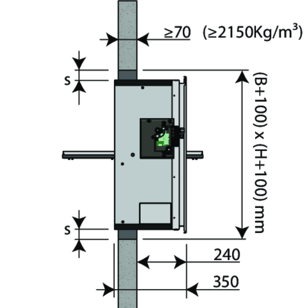
Make an opening with dimensions (W+20) x (H+20) mm till (W+100) x (H+100) mm.
Mount the damper in the opening. The joint between the damper and the shaft (S) needs to be filled right across the width of the duct with a standard concrete mortar.
Support the body and block the damper blade in its closed position to prevent deformation of the body during the drying process of the sealing.
Fix the grill to the flange using glue type Polyflex.
Check the movement of the damper blade.
Test the mechanism of the damper.
General remarks
- The installation must comply with the installation manual and the classification report.
- The installation of the smoke control duct must comply with the classification report delivered by the manufacturer.
- Axis orientation: see the declaration of performance.
- Avoid the obstruction of adjoining smoke control ducts.
- Verify if the blade can move freely.
- Rf-t smoke dampers may be applied to smoke control ducts that have been tested according to EN 1366-8 and EN 1366-9 as appropriate, constructed from similar materials with a fire resistance, thickness and density equal or superior to these of the tested materials.
- Caution: when fitting, the product should be handled with care and remain protected from any sealing products.
- Caution: before putting the installation into operation, clean off all the dust and dirt.
- Caution: bear in mind the blade’s clearance inside the smoke control duct.