VT60 - Installation
Operation: manual closing
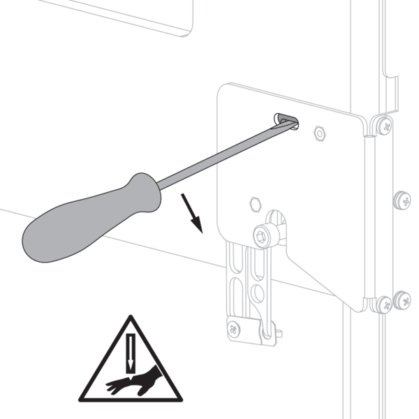
Unlock the mechanism by lifting the locking plate through the slotted hole with the help of a flat screwdriver. This action makes the shutter blade fall.
Watch out for the fingers!
Operation: manual opening
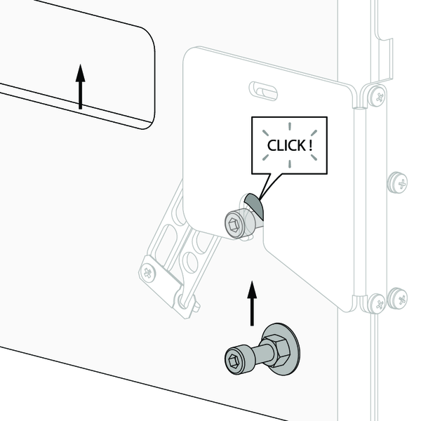
Lift the shutter blade with two hands by the integrated handles until the lock bolt snaps into the open lock.
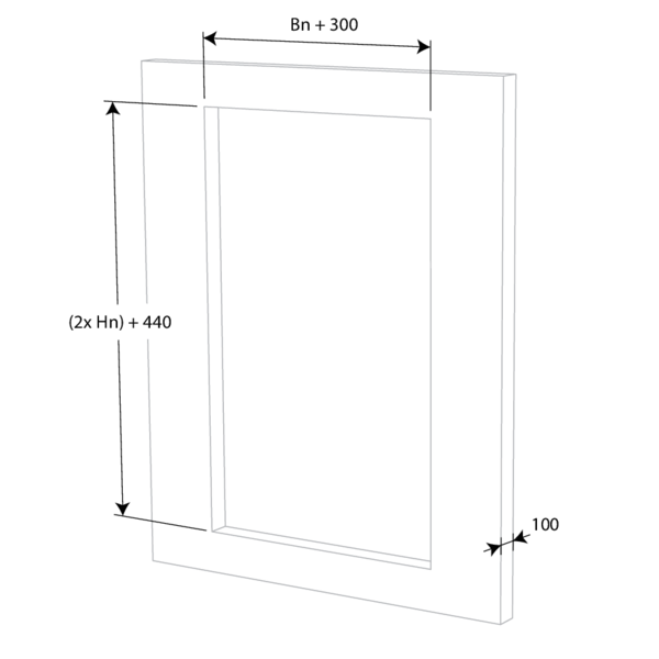
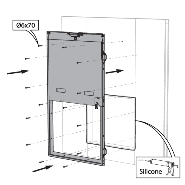
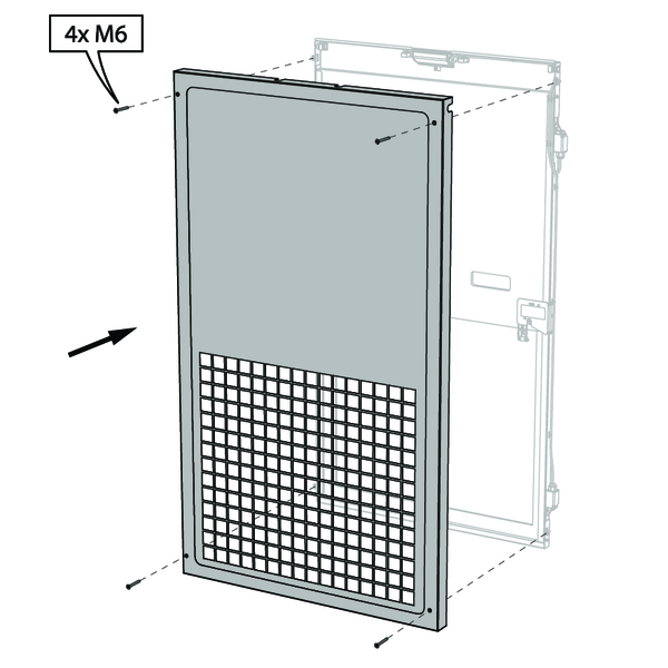
Installation in rigid wall
The product was tested and approved in:
- Aerated concrete ≥ 100 mm | EI 60 | Not applicable | Type of installation: surface-mounted with grill (fire side opposite the grill) | 300x200 mm ≤ VT60 ≤ 800x800 mm
- Aerated concrete ≥ 100 mm | E 60 | Not applicable | type of installation: surface-mounted, without grill | 300x200 mm ≤ VT60 ≤ 800x800 mm
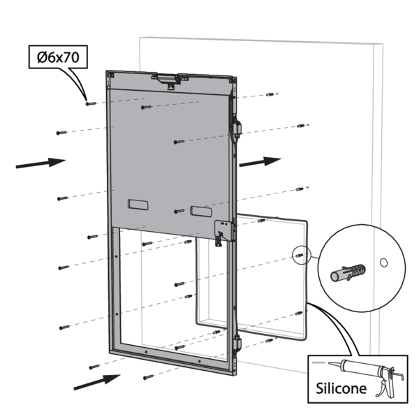
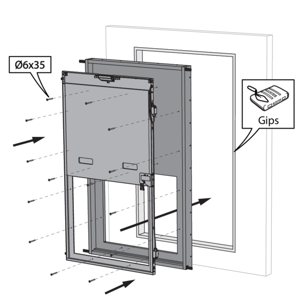
Installation in rigid wall by means of mounting frame E-VT60
The product was tested and approved in:
- Aerated concrete ≥ 100 mm | EI 60 | Not applicable | Type of installation: surface-mounted with grill (fire side opposite the grill) | 300x200 mm ≤ VT60 ≤ 800x800 mm
- Aerated concrete ≥ 100 mm | E 60 | Not applicable | type of installation: surface-mounted, without grill | 300x200 mm ≤ VT60 ≤ 800x800 mm
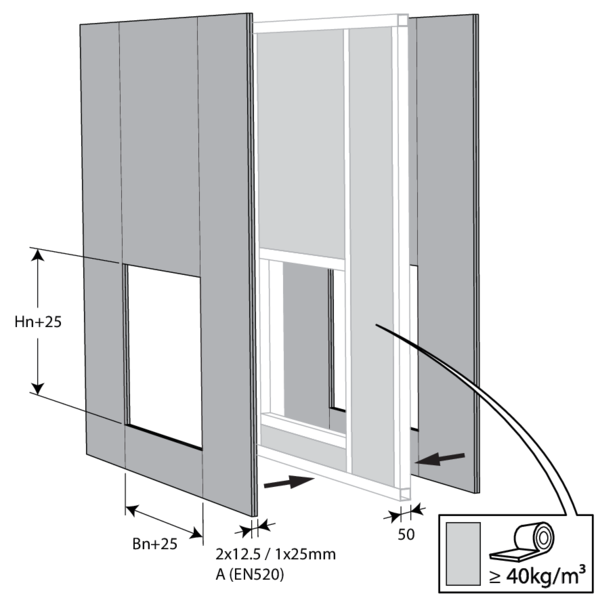
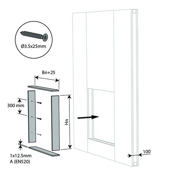
Installation in flexible wall (metal stud gypsum plasterboard wall)
The product was tested and approved in:
- Metal studs gypsum plasterboard Type A (EN 520) ≥ 100 mm | EI 60 | Not applicable | Type of installation: surface-mounted with grill (fire side opposite the grill) | 300x200 mm ≤ VT60 ≤ 800x800 mm
- Metal studs gypsum plasterboard Type A (EN 520) ≥ 100 mm | E 60 | Not applicable | type of installation: surface-mounted, without grill | 300x200 mm ≤ VT60 ≤ 800x800 mm
Electrical connection (only when the shutter is equipped with limit switches)
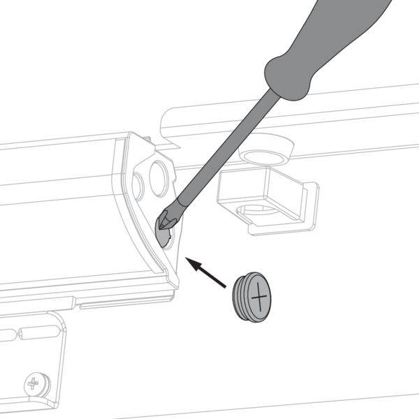
Pierce an opening in the connection box. Affix the grommet delivered with the product.
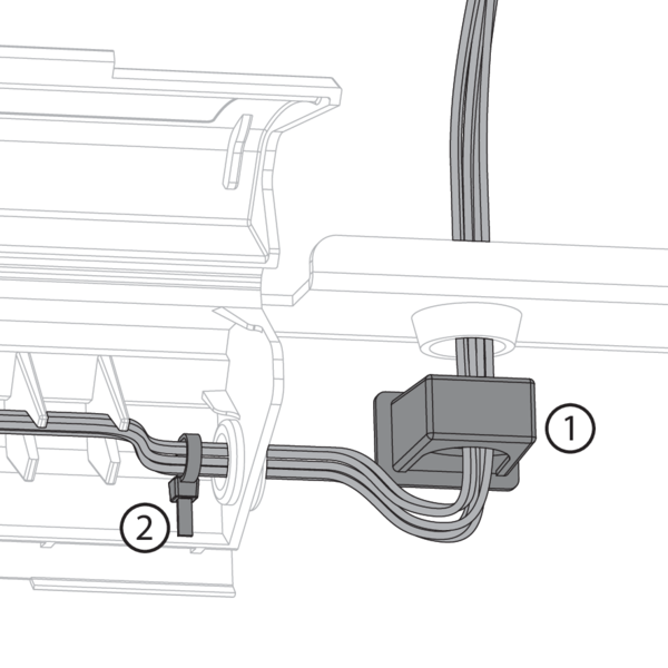
Lead the cables through the opening. Use the fixation clip (1) and the plastic cable clamp (2) to attach the cables in the connection box and connect according to the electrical connection diagram.
Comply with the installation rules according to article 6.1 of NF S 61-932.
Comply with the installation rules according to article 6.1 of NF S 61-932.
Replacement fusible link FUS72 VT60
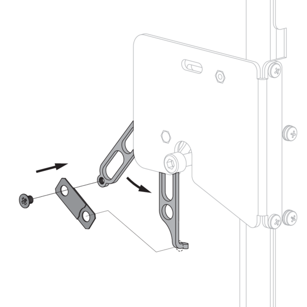
Unscrew the mounting bolt. Remove the old fusible link. Attach the new fusible over the hook and secure it with the mounting bolt.
General remarks
- The installation must comply with the installation manual and the classification report.
- Verify if the blade can move freely.
- Caution: when fitting, the product should be handled with care and remain protected from any sealing products.
- Caution: before putting the installation into operation, clean off all the dust and dirt.